Installation template – OpenEye CM-306 User Manual
Page 2
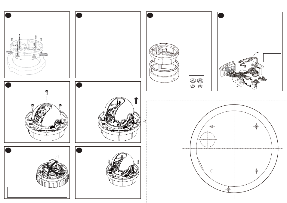
Installation
Template
Prepare the dome for installation
Connect the wiring
1. Loosen the four cover screws with the supplied Torx driver and remove the dome
cover.
2. Loosen the gimbal securing screws to remove the camera module.
3. Select a mounting method below--A, B, or C.
1. Connect
F1 and F2 to your video-out and power-in cables.
2. If needed, use
F8 (wire-ended adapter lead) with power supply cables.
Note 12vDC: connect the red lead to +ve and black lead to -ve.
24vAC: Connect either way, polarity is not important.
3. Connect the camera to
F4.
4. To focus the camera, use
F3, a service jack for temporary video connection.
1
4
Use template to prepare mounting area
Flush Mount
• Tape the template to the mounting surface and cut a 4.3” hole as indicated by
T5
on the template.
A. Using Screws:
Using a ¼” (7mm) drill bit, drill two holes at template positions
T2 and insert a
wall anchor in each hole. Use two (no. 12 x 1 ½”) screws to secure the camera to
mounting surface.
B. Using Locking Arms:
Place the camera (with the locking arms retracted) into the opening. Use a Phillips
head screwdriver to turn the silver-colored screws (
B1) clockwise to first extend
the locking arms and then tighten them against the mounting surface. Tighten the
screws sufficiently to compress the o-ring seals under the screw heads, however -
DO NOT OVERTIGHTEN.
Surface Mount
C. Surface Mount:
Tape the template to the mounting surface and using a ¼” (7mm) drill bit, drill four
holes at template positions
T1 and insert a wall anchor in each hole. Use four (no.
12 x 1 ½”) screws to secure the camera to mounting surface. If you are install-
ing the camera outside, use a rubber o-ring with each screw to ensure moisture
resistance.
Note When flush mounting or surface mounting using the outer ring, ensure that the
large rubber gasket (
E6) is in place under the lip of the dome enclosure.
Note Do not attempt to adjust the camera position by holding the lens. This
will damage the camera. Make adjustments by tilting and rotating the
gimbal assembly. DO NOT rotate/tilt the disk beyond its maximum
allowed range (350/87 degrees), you may damage the camera.
2
A
A
C
C
C
C
B1
B1
B1
B1
A
Flush mount using screws.
B
Flush mount using locking
arms.
C
Surface mount using outer
ring and rubber o-rings.
T3
T4
T2
T2
T1
T1
T1
T5
T1
• To avoid damage to the lens
mount, tilt and pan the lens by
holding onto the two bars (
I2) on
the disk. DO NOT USE THE LENS
TO POSITION THE CAMERA.
• Rotate and pan the camera chas-
sis (
I1) to the desired position.
Fit camera assembly
Adjust camera position and test
Replace camera liner & dome cover
Remove camera liner
• Place the complete camera assembly (
G1) onto
the three mounting pillars (
G2) and tighten the
gimbal screws.
• Rotate and pan the camera chassis to the desired position
and then tighten the camera chassis locking screws.
• Replace the dome cover. Four small internal rigs in the cover align with four
corresponding index slots (
E7) on the enclosure body. These restrict the cover to
only four possible orientations and ensure that the cover screw holds are correctly
aligned. Use the included Torx key to tighten the four cover screws. DO NOT
OVERTIGHTEN.
• Carefully place the camera liner (
J1)
over the focused camera so that it
fits fully on the top ring of the camera
chassis (
J2) and provides an
unobstructed view for the camera
lens.
• Lift the camera liner (
H1) from the chassis (H2)
to provide full access to the camera.
5
7
8
6
F1: Video output
F2: Power 12vDC or 24vAC input
F3: Service jack
F4: Camera lead fly connector
F5: Cable trap pillar, washer and screw
F6: RS-485 / Alarm / Light
F7: OSD controller connector
F8: Wire-ended power adapter lead
F9: OSD lead to camera
Open the necessary cable entry
• There are two cable entry options: base cable entry (
E1), or side cable entry (E3).
• For surface mount, use
E3 to go with either E4 or E5.
• Rotate the outer ring as necessary to align knock-outs with side cable entry.
• Unused cable entries should be blocked with sealing plugs (
E8).
• For indoor installations without conduit, the cable entry grommet (
E9) should be
used to prevent dust ingress.
• For outdoor installations, conduit should be used to carry cables to the housing.
Mounting Methods
There are three mounting methods available for this camera:
A: Flush Mount using screws
B: Flush Mount using locking arms
C: Surface Mount using the outer ring
Note Always use the template provided.
3
E1
E3
E2
E4
E6
E7
E7
E7
E7
E5
E1: Threaded base cable entry
(¾” sealing plug (E8) and cable
entry grommet (E9) supplied
E2: Washer and screw cable retainer
E3: Threaded side entry (with ½”
sealing plug (E8) fitted
E4: Outer ring large knock-out for
conduit entry
E5: Outer ring small knock-out for
cable only entry
E6: Large rubber gasket
E7: Cover index slots
E8: Cable entry sealing plugs
E9: Cable access grommet
T1: Drill ¼” holes for Surface Mount
T2: Drill ¼” holes for Flush Mount (using screws)
T3: Location of base cable entry
T4: Location of side cable entry
T5: 4.3” hole for Flush Mount
H1: Camera liner
H2: Camera chassis
J1: Camera liner
J2: Camera chassis
E8
E9
F4
F5
F3
F7
F9
12VDC
GND
F2
F1
F8
F6
NEC Class 2 / LPS
Supply Required
G2
G2
G2
G1
I1
I2
H2
H1
J1
J2