OpenEye 200-Series Installation Manual User Manual
Page 2
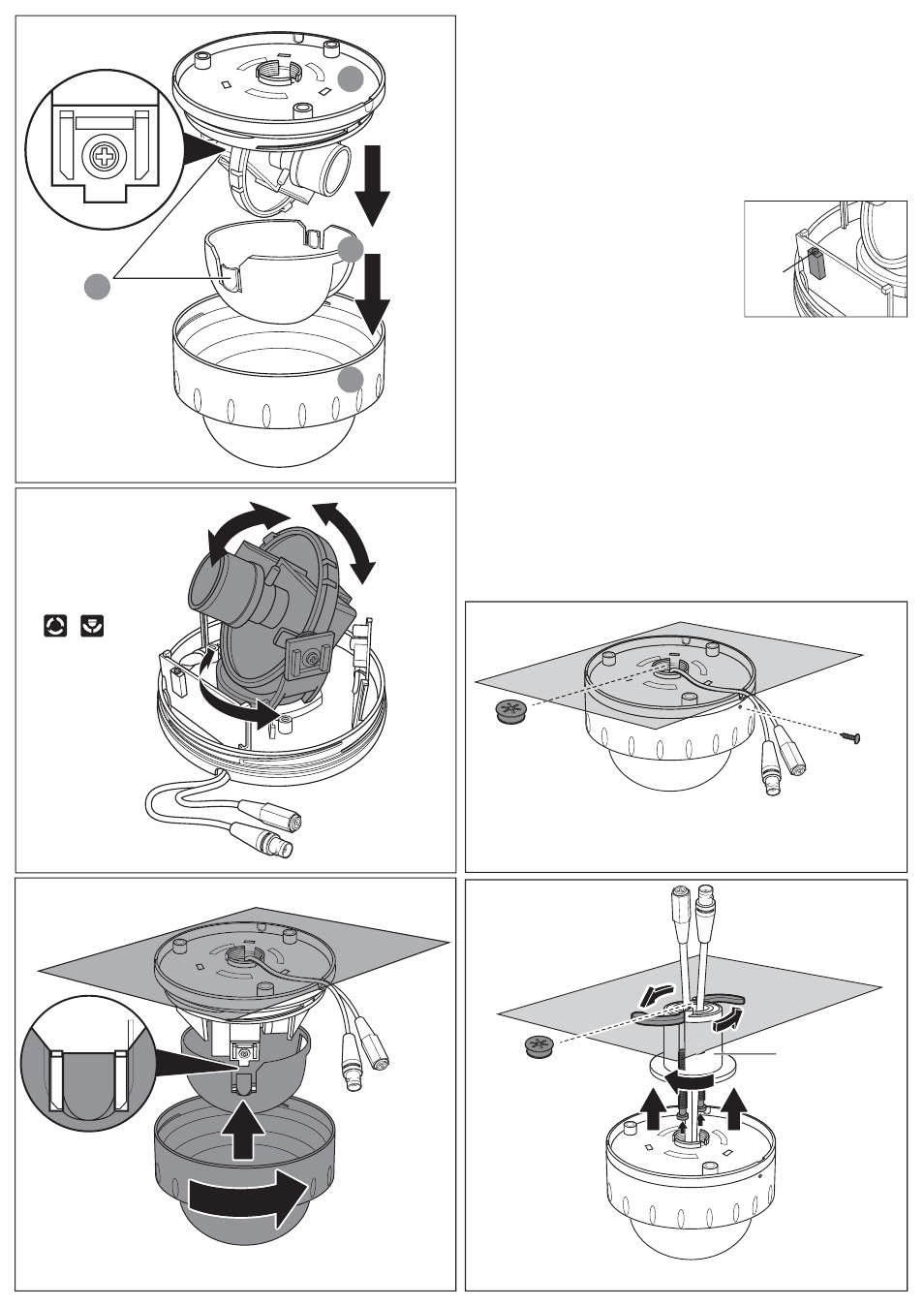
Installing the Dome Enclosure
Service jack
socket
E1
E2
F1: Camera liner
F2: Dome cover
F
F1
F2
D
D1: Dome base
D2: Camera liner
D3: Dome cover
D4: Notches (on both sides)
D1
D2
D3
D4
Rotate and tilt the camera
base to the required position.
E
360º
rotate
83º
tilt
G1: Video Output Connector
G2: Power Input Connector
G3: Cable entry sealing plug (3/4”)
T6 screw
G2
G1
G3
G
H1
H2
H1: Quick install adaptor
H2: Cable entry sealing plug (1/2”)
H
Push the camera liner
up to the base until it
clicks into place.
1. Remove the dome cover and the camera liner
Gently turn the dome cover counter-clockwise to unlock and pull free of the dome base. Remove
the camera liner by gently pulling it free of the two notches (D4) in the camera base (see fig D).
2. Use the template to mark-out and prepare the mounting area
When mounting the dome to a ceiling or wall using screws, first knock out the screw access holes
(C2) that correspond to the template marks “D5”. This can be done by using a cross-point
screwdriver. When mounting the dome to a ceiling using the quick install adaptor, use the
template to cut a hole as the circle marked “T5” with a hole cutter.
3. Open the required knock-out panel
Use a sharp knife or side cutter pliers to cut one of the side knock-outs (C3) to the size required to
allow cable entry. Be careful not to hurt yourself or damage the camera when using knives and
side cutter pliers.
4. Mount the dome enclosure
Using one of the mounting schemes discussed on the
other side of this sheet (Methods for mounting the enclo-
sure), fix the dome enclosure in place.
5. Connect the wiring
Feed the pre-connected main lead (that feeds into the
connections G1 and G2) through the appropriate point and
connect it to your video out and power in cables. A service
jack socket is also provided for temporary video connection
when focusing the camera, using an optional service cable
(CA-MON/BNC).
6. Adjust the camera position
You can adjust the focusing position by rotating and panning the camera base (see fig E).
7. Install the camera liner
Carefully fit the camera liner (F1) over the camera base so that it snaps into place as shown in fig.
F and does not obstruct the camera lens.
8. Replace the dome cover
a. Install 3/4” cable entry sealing plug (G3) on the dome base.
b. Push the cables (G1 and G2) through the dome base and 3/4” cable entry sealing plug (G3),
make sure the sealing plug is properly installed on the base.
c. Replace the dome cover (F2) and rotate to close it as shown in fig F. Use the supplied T6 screw
to secure the whole enclosure (see fig. G)
9. Using the quick install adaptor see figure H
a. Install 1/2” cable entry sealing plug (H2) on quick install adaptor (H1). Push the quick install
adaptor into the appropriate cut out hole.
b. Use the screws to adjust the position of the two locking arms (B1) on the quick install adaptor to
adjust to the mounting surface.
c. Push the cables through the opening (H1) and 1/2” cable entry sealing plug (H2), make sure the
sealing plug is properly installed on the adaptor;
d. Thread the dome onto the quick install adaptor. This takes about 1½ turns. DO NOT OVER-
TIGHTEN.