Section 4: wiring, Installation, Left-side view right-side view – Montigo RP620 User Manual
Page 17
RP620 Power Vent Indoor Gas Fireplace
Page 17
XG0777 - 122014.1
Installation
Installation of Electrical Supply
The
RP620* is supplied with an external electrical control box pre-
wired by the factory. The control box is connected to the fireplace
with a 30 foot long 6-conductor cable that will communicate with
the fireplace. Extension cables are available through your Montigo
Dealer only.
A 20ft low voltage black / white cable is provided for connection
to a single pole on/off switch. The length of this cable can be
extended up to a length of 100ft using a cable of equal or greater
capacity. This system operates on 24VAC. Do not connect this
switch circuit to an external power source.
Optional remote control available through your Montigo Dealer.
Do not use third party remote controls without the approval from
Montigo.
Section 4: Wiring
Installing the Fireplace Control Box
Install the Fireplace Control Box in an accessible location. The
location should be where maintenance, adjustments and service
may be made easily.
Conduit & Wiring clearances
Connect the power vent harness as outlined in the previous section.
Ensure that the proper clearances are maintained for the wiring and
conduit. When installing the wiring it must never run above the vent
run and it must be at least 1" clear of all venting.
1” Clearance
Wire
Note: If any of the original wire supplied with the appliance is
replaced, it must be with the same or it's equivalent.
Installations in Canada must be electrically grounded in
accordance with
CSA C22.1 Canadian Electrical Code Part 1
and/or Local Codes.
Installations in the USA must be electrically grounded in
accordance with local codes or, in the absence of local codes,
with the National Electrical Code,
ANSI/NFPA 70.
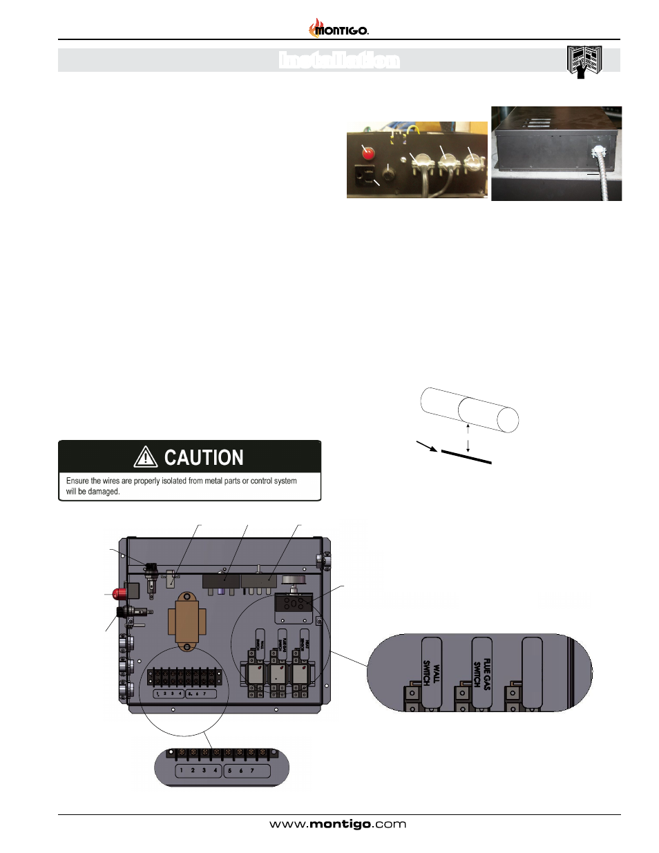
Figure 11. Control Box
Left-side View
Right-side View
Power Vent
Harness
Power Vent
Speed Control
Post Purge
Timer (3 min.)
Prepurge
Timer (1 min.)
Power
Vent Fuse
(5A)
Power Vent
Connector
Control
Panel Fuse
(5A)
LED
Power
Indicator
Heat Sensor /
Conmustion Switch
Figure 12. Conduit and Wiring
LED Indicator
Fuse
115V
Power Supply
Wall Switch Control
cable
115V
Outlet
Figure 10. Control box Diagram