Full-bridge i – Measurement Computing 6224 User Manual
Page 32
6224 User’s Manual
Strain and Pressure/Force 7-7
Full-Bridge I
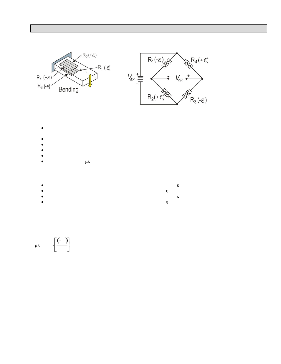
The Full-bridge type I only measures bending strain.
Full-bridge type I configuration has the following characteristics:
Four active strain-gauge elements. Two are mounted in the direction of bending strain on one side of the strain
specimen (top), the other two are mounted in the direction of bending strain on the opposite side (bottom).
Highly sensitive to bending strain.
Rejects axial strain.
Compensates for temperature.
Compensates for lead resistance.
Sensitivity at 1000
is ~ 2.0 mV
out
/ V
EX
input.
The following symbols apply to the above circuit diagram and to the equations provided in the supplemental information.
R1 is an active strain-gauge element measuring compressive strain (– ).
R2 is an active strain-gauge element measuring tensile strain (+ ).
R3 is an active strain-gauge element measuring compressive strain (– ).
R4 is an active strain-gauge element measuring tensile strain (+ ).
Supplemental Information
Data from strain channels (Full-Bridge I) is converted to strain units using the following equation:
10
6
V r
GF