3 - pinouts and connections, Strain channels, rj50 pinout, Pinouts and connections 3 – Measurement Computing 6224 User Manual
Page 15
6224
User’s Manual
Pinouts and Connectors 3-1
Pinouts and Connections
3
Strain Channels, RJ50 Pinout
…… 3-1
Bridge Connections …… 3-2
Connecting TEDS Channels …… 3-2
Remote Sensing …… 3-2
Shunt Calibration …… 3-3
Internal Excitation Voltage Sources …… 3-3
External Excitation Voltage Sources …… 3-4
Mounting and Securing Connections …… 3-5
Where to Find Additional Information …… 3-5
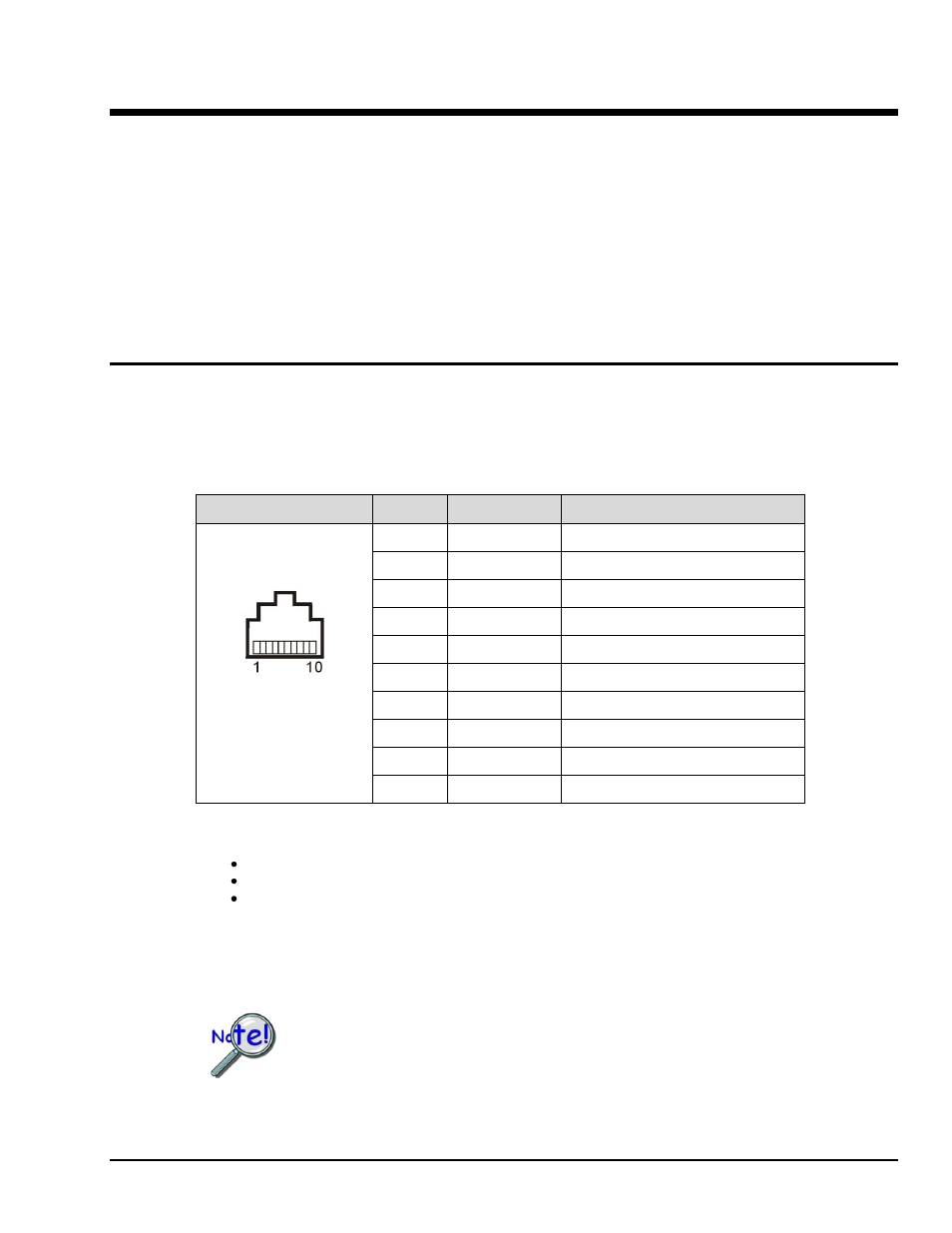
Strain Channels, RJ50 Pinout
The twelve RJ50 (10p10c) jacks each have 10 pins with signal designations as indicated in the following table.
RJ50 (10p10c) Modular Plug and Jack Pinout
Pin #
Signal Name
Signal Description
RJ50
Front View
1
SC
Shunt Calibration
2
AI+
Positive Input Signal
3
AI-
Negative Input Signal
4
RS+
Positive Remote Sense Signal
5
RS-
Negative Remote Sense Signal
6
EX+
Positive Excitation Signal
(Note 1)
7
EX-
Negative Excitation Signal
(Note 1)
8
T+
TEDS DATA
(Note 2)
9
T-
TEDS Return
(Notes 1 & 2)
10
SC
Shunt Calibration
Note 1: The three channel blocks each share three signals [within their block], as follows:
For CH1, CH2, CH3, and CH4, the signal values of pins 6, 7, and 9 are shared.
For CH5, CH6, CH7, and CH8, the signal values of pins 6, 7, and 9 are shared.
For CH9, CH10, CH11, and CH12, the signal values of pins 6, 7, and 9 are shared.
Note 2: The 6224 only supports TEDS if the acquisition software being used supports TEDS.
Do not connect an RJ45 plug to an RJ50 jack. Using RJ45 plugs can
cause permanent damage to RJ50 pins 1 and 10, thus disabling shunt
calibration.