Specifications, Output specifications, Power – Measurement Computing USB-ERB08 User Manual
Page 19: Specifications -1, Output specifications -1, Power -1, Chapter 4
Chapter 4
Specifications
Typical for 25 °C unless otherwise specified.
Specifications in italic text are guaranteed by design.
Output specifications
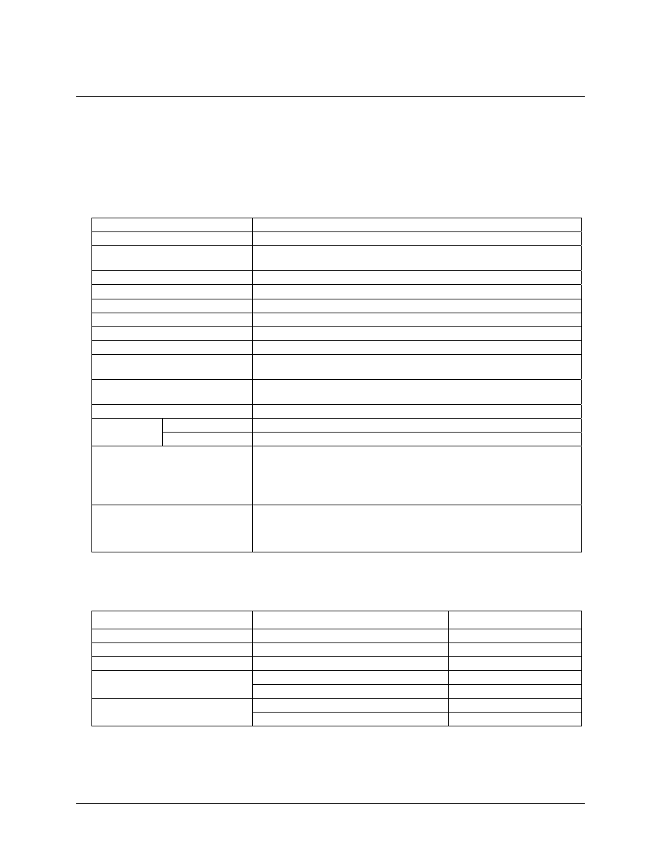
Table 1. Output specifications
Number of relays
8
Relay configuration
2 banks of 4
Contact configuration
8 Form C (SPDT) Normally Open, Normally Closed and Common available at
screw terminals
Contact rating
6 A @ 240 VAC or 28 VDC resistive
Contact resistance
100 milliohms max (initial value)
Operate time
10 milliseconds max
Release time
5 milliseconds max
Vibration
10 to 55 Hz (amplitude 1.5 mm)
Shock
10 G (11 milliseconds)
Dielectric isolation (between relay
open contact)
300 VAC, 50/60 Hz (1 minute)
Dielectric isolation (between PCB
output lines)
500VAC, 50/60 Hz (1 minute)
Life expectancy
10 million mechanical operations, min
S2 = pull-up
Energized. NO in contact with Common
Power on state
S2 = pull-down
Not energized. NC in contact to Common
Relay control logic polarity
User-configurable per bank via switch S1 for invert or non-invert (default).
Switch settings for polarity can be read back via software through the USB bus.
Switch settings do not affect the power on condition. Non-invert mode: when "0"
is written or read back via the USB bus, relays are not energized. Invert mode:
when "0" is written or read back via the USB bus, relays are energized.
Pull-up / pull-down (controls relay
power on state)
User-configurable per bank via switch S2 for pull-down (default) or pull-up.
Switch settings can be read back via software. Pull-down will put the relays in
non-energized mode on power up. Pull-up will put the relays in energized mode
on power up.
Power
Table 2. Power specifications
Parameter Conditions
Specification
USB +5 V input voltage range
4.75 V min. to 5.25 V max.
USB +5 V supply current
All modes of operation
10 mA max
External power supply (required)
MCC p/n CB-PWR-9
9 V ±10% @ 1 A
V
ext
< 6.0 V
,
V
ext
> 12.5 V
PWR LED = Off (power fault)
Voltage supervisor limits - PWR LED
6.0 V < V
ext
< 12.5 V
PWR LED = On
All relays on, 100 mA downstream hub power
750 mA typ, 850 mA max
External power consumption
All relays off, 100 mA downstream hub power
170 mA typ, 200 mA max
4-1