External power connectors, Usb led, Pwr led – Measurement Computing USB-ERB08 User Manual
Page 15: Invert/non-invert switch (s1), External power connectors -2, Usb led -2, Pwr led -2, Invert/non-invert switch (s1) -2
USB-ERB08 User's Guide
Functional Details
External power connectors
The USB-ERB08 has two external power connectors labeled
POWER IN
and
POWER OUT
on the enclosure.
The
POWER IN
connector is labeled
PWR IN
on the board, and the
POWER OUT
connector is labeled
PWR
OUT
on the board.
Connect the
POWER IN
connector to the supplied +9 V external power supply. External power is required to
operate the USB-ERB08. The
POWER OUT
connector lets you power additional daisy chained MCC USB
Series products from a single external power supply. Depending on your load requirements, daisy chained
products may require a separate power supply. Refer to "
Power limitations using multiple USB-ERB08
" on page 3-4 for more information.
USB LED
The
USB
LED indicates the communication status of the USB-ERB08. It uses up to 5 mA of current and cannot
explains the USB LED function.
Table 3-2. USB LED Illumination
USB LED
illumination
Indication
Steady green
The USB-ERB08 is connected to a computer or external USB hub.
Pulsing green
Initial communication is established between the USB-ERB08 and the computer, or data is being
transferred.
PWR LED
The USB-ERB08 incorporates an on-board voltage supervisory circuit that monitors the external 9 V power. If
the input voltage falls outside of the specified range, the
PWR
LED shuts off.
the PWR LED.
Table 3-3. PWR LED Illumination
PWR LED
illumination
Indication
Steady green
External power is supplied to the USB-ERB08.
Off
Power is not supplied by the external supply, or a power fault has occurred. A power fault occurs
when the input power falls outside of the specified voltage range of the external supply (6.0 V to
12.5 V).
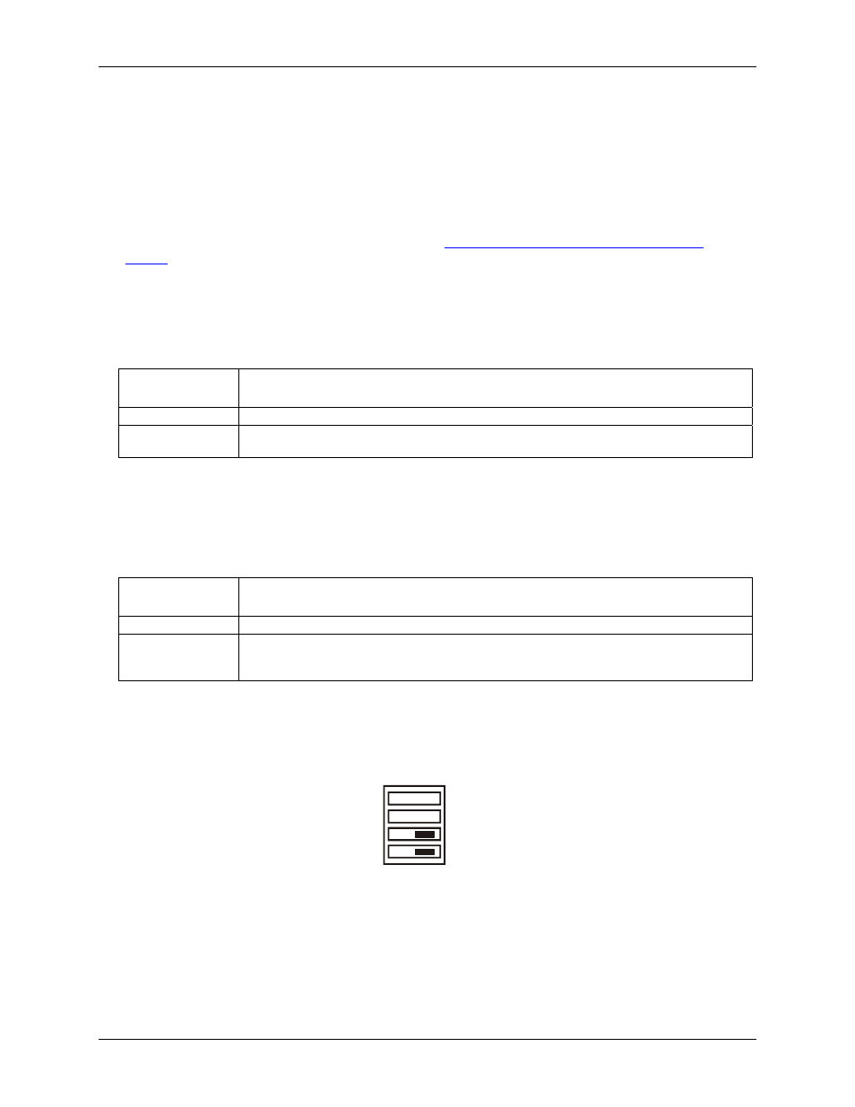
Invert/Non-invert switch (S1)
The Invert/non-invert switch (S1) sets the relay control logic per relay bank to either inverted or non-inverted.
By default, switch S1 is configured for non-invert (see
).
NON-INVERT
INVERT
CH
CL
S1
Figure 3-2. Switch S1 default configuration
The switch labeled
CL
configures relays 1 through 4, the switch labeled
CH
configures relays 5 through 8.
NON-INVERT
: when "0" is written or read back via the USB bus, the relays are not energized.
INVERT
: when "0" is written or read back via the USB bus, the relays are energized.
Switch settings do not affect the power-on condition. Use InstaCal to read the current logic setting for each
module group.
3-2