Relay configuration, Relay configuration -5 – Measurement Computing USB-ERB08 User Manual
Page 18
USB-ERB08 User's Guide
Functional Details
Relay configuration
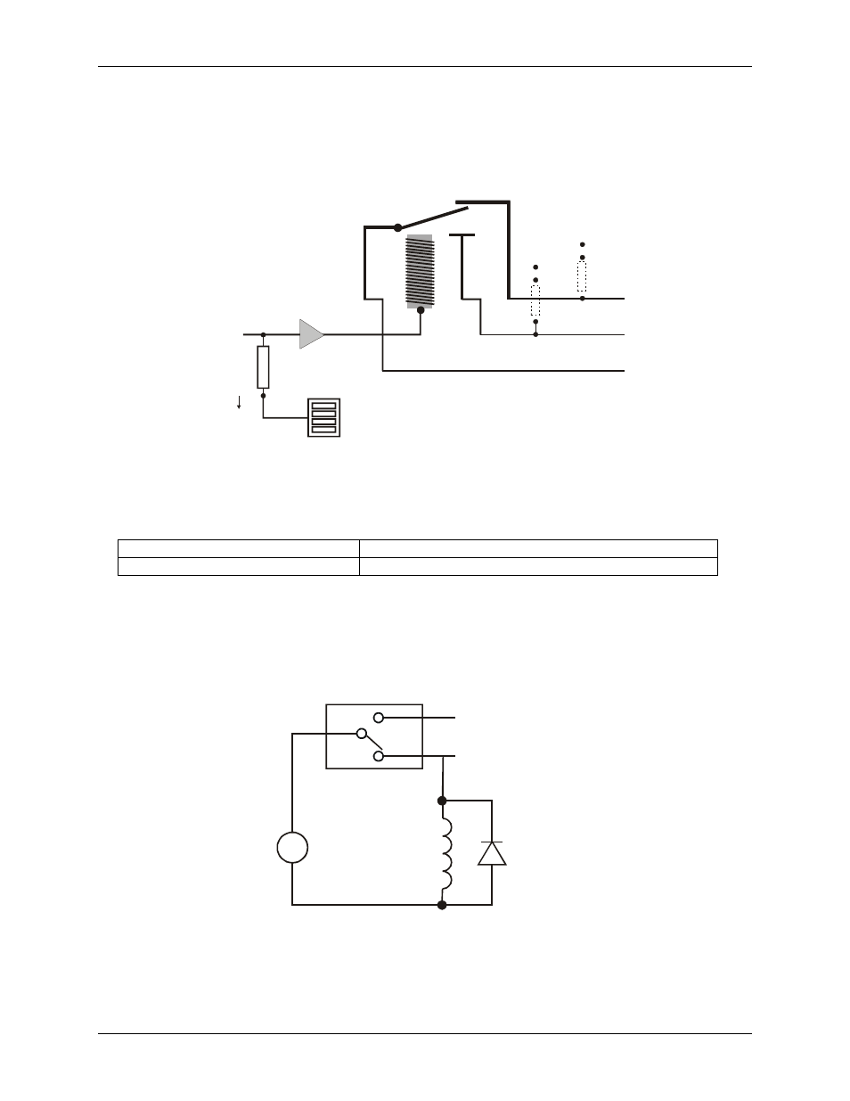
You can install a pull-up or pull-down resistor at the NO and NC terminals on each relay. Note that the pull-up
resistors are tied to the 5 V power and should be considered when calculating the power budget. The relay
configuration is illustrated in the following schematic.
User-installed
pull-up / pull-down resistor
GND
+5
Screw
terminals
(3 per
relay)
GND
+5
C
NO
NC
Digital output
from the user
Buffer/
driver
10 k
resistor
Pull-up/pull-down
switch S2
Figure 3-6. Relay configuration
The relay contacts associated that are with each relay location are listed in
Table 3-4. Relay locations and associated contacts
R1, R3, R5, R7, R10, R12, R14, R16
Relays NO contact pull-up (to USB +5 V) / pull-down
R2, R4, R6, R8, R9, R11, R13, R15
Relays NC contact pull-up (to USB +5 V) / pull-down
Relay contact protection circuit for inductive loads
When you connect an inductive load to a relay, energy stored in the inductive load can induce a large voltage
surge when you switch the relay. This voltage can severely damage the relay contacts. To limit the voltage
surge across the inductive load in a DC circuit, install a kickback diode across the inductive load. Refer to the
contact protection circuit in F
. For AC loads, install a metal oxide varistor (MOV).
Figure 3-7. Relay contact protection circuit
C
V
Inductive
Load
Kickback
Diode
NC
+
-
NO
Relay
3-5