Power limitations using multiple usb-erb08 devices, Voltage drop, Voltage drop -4 – Measurement Computing USB-ERB08 User Manual
Page 17: Power limitations using multiple usb-erb08, Devices, Ge 3-4 fo
USB-ERB08 User's Guide
Functional Details
1.
2.
3.
Connect the
POWER OUT
connector on the connected module to the
POWER IN
connector on the new
module.
This step is required only if you plan to daisy chain power to another module.
Connect the
USB OUT
connector on the connected module to the
USB IN
connector on the new module.
To add another module, repeat steps 1-2, with the module you just connected now being the connected
module.
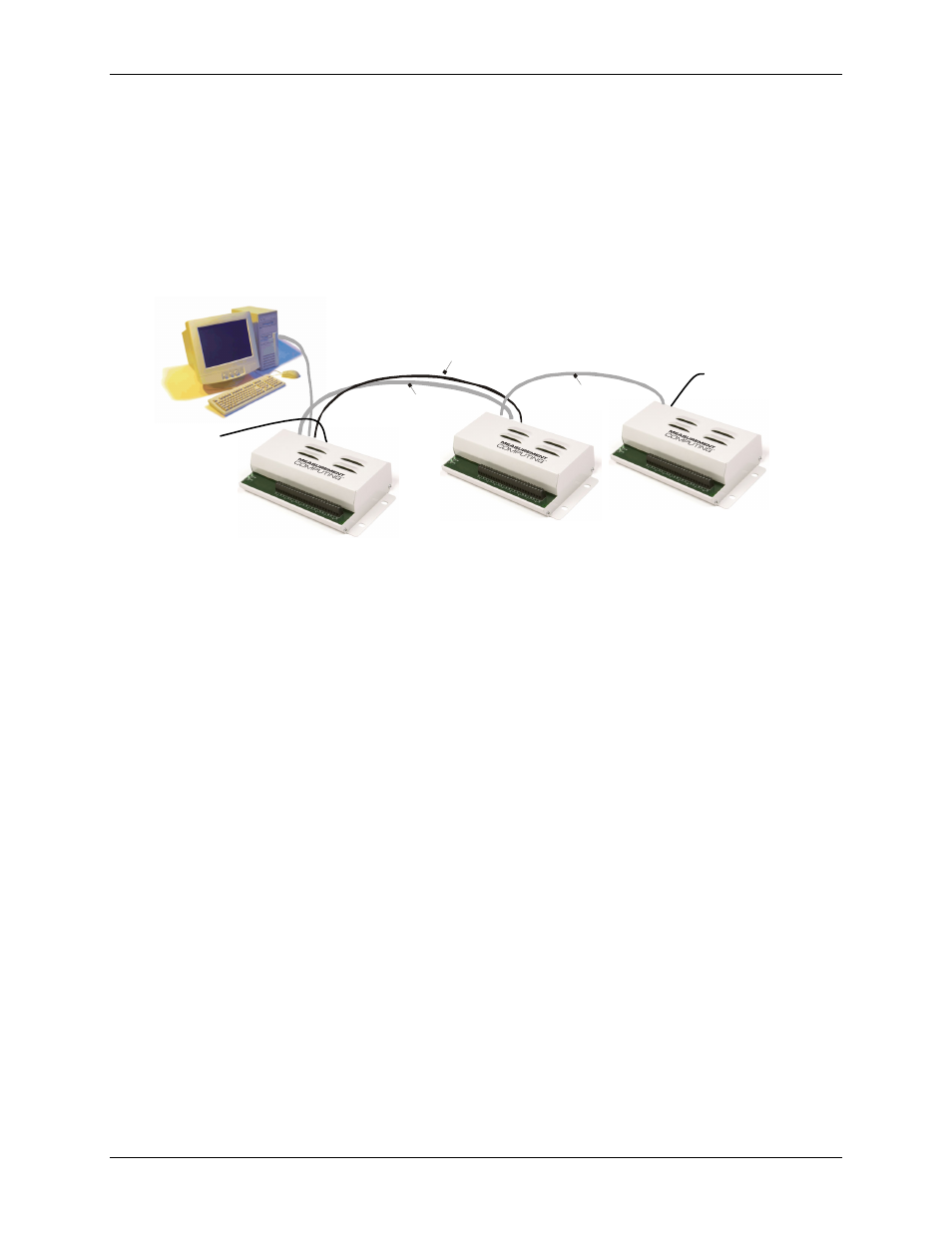
A daisy chain example is shown in
. Note that the last board in the chain is supplied with external
power.
Figure 3-5. Daisy chain connections
USB port to
USB IN
USB OUT
to USB IN
USB OUT
to USB IN
POWER OUT
to POWER IN
CB-PWR-9
supply
to POWER IN
CB-PWR-9
supply
to POWER IN
Power limitations using multiple USB-ERB08 devices
When daisy chaining additional MCC USB Series products to the USB-ERB08, you must ensure that you
provide adequate power to each board that you connect. The USB-ERB08 is powered with a 9 VDC nominal,
1.0 A external power supply.
When connecting multiple modules, power supplies with higher current capability, such as the CB PWR-9V3A,
are available from MCC.
Voltage drop
A drop in voltage occurs with each board connected in a daisy chain system. The voltage drop between the
power supply input and the daisy chain output is 0.5 V maximum. Factor in this voltage drop when you
configure a daisy chain system to ensure that at least 6.0 VDC is provided to the last board in the chain.
3-4