Additional documentation, Unpacking the usb-erb08, Installing the software – Measurement Computing USB-ERB08 User Manual
Page 11: Installing the usb-erb08, Configuring the hardware switches, Additional documentation -2, Unpacking the usb-erb08 -2, Installing the software -2, Installing the usb-erb08 -2, Configuring the hardware switches -2
USB-ERB08 User's Guide
Installing the USB-ERB08
Additional documentation
In addition to this hardware user's guide, you should also receive the Quick Start Guide (available in PDF at
). This booklet supplies a brief description of
the software you received with your USB-SSR08 and information regarding installation of that software. Please
read this booklet completely before installing any software or hardware.
Unpacking the USB-ERB08
As with any electronic device, you should take care while handling to avoid damage from static
electricity. Before removing the USB-ERB08 from its packaging, ground yourself using a wrist strap or by
simply touching the computer chassis or other grounded object to eliminate any stored static charge.
If your USB-ERB08 is damaged, notify Measurement Computing Corporation immediately by phone, fax, or e-
mail. For international customers, contact your local distributor where you purchased the USB-ERB08.
Phone: 508-946-5100 and follow the instructions for reaching Tech Support.
Fax: 508-946-9500 to the attention of Tech Support
Email:
Installing the software
Refer to the Quick Start Guide for instructions on installing the software on the Measurement Computing Data
Acquisition Software CD. This booklet is available in PDF
Installing the USB-ERB08
Before you connect the USB-ERB08 to your computer, configure the hardware and then connect the external
power supply that was shipped with the device.
Configuring the hardware switches
The USB-ERB08 has two on-board switches that you set to configure the relay control logic polarity and
relay
power-on
state
. Factory-configured default settings are listed in Ta
. Refer to
for the location of
each switch on the USB-ERB08.
Table 2-1. Default switch configuration
Board label
Description
Default setting
INVERT NON-INVERT
S1
Configures the relay control logic parity per relay bank for invert or
non-invert logic.
Non-invert
Pull DOWN PULL UP
S2
Configures the relay power-on state per relay bank for pull-up or
pull-down.
Pull down
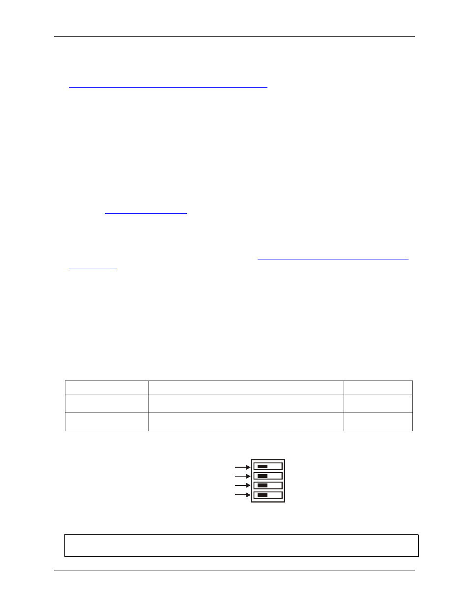
Each DIP switch sets the configuration of one relay group. The switch labeled
CL
configures relays 1 through 4,
the switch labeled
CH
configures relays 5 through 8.
CH
CL
No function
No function
Configures relays 5-8
Configures relays 1-4
Figure 2-2. Typical board switch
Port CL consists of relays 1 through 4, and Port CH consists of relays 5 through 8.
Remove from the enclosure to access the on-board switches
To change the configuration of a switch, you must first remove the USB-ERB08 from the enclosure.
2-2