Relay control logic parity, Relay power-on state, Connecting the external power supply – Measurement Computing USB-ERB08 User Manual
Page 12: Connecting the external power supply -3
USB-ERB08 User's Guide
Installing the USB-ERB08
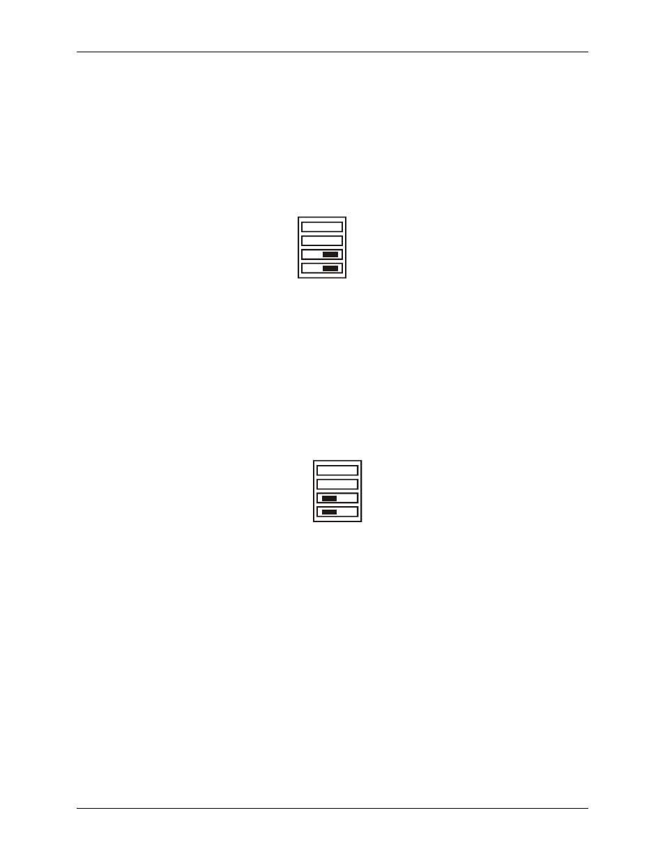
Relay control logic parity
Configure the
Invert/non-invert
switch (S1) to set the relay control logic polarity for each relay bank for invert
or non-invert. By default, this switch is shipped with all banks configured for non-inverted logic, as shown in
Figure 2-3. Invert/non-invert switch (S1)
NON-INVERT
INVERT
CH
CL
S1
PULL UP
PULL DOWN
CH
CL
NON-INVERT
mode: when "0" is written or read back via the USB bus, the relays are not energized.
INVERT
mode: when "0" is written or read back via the USB bus, the relays are energized.
Switch settings for polarity can be read back via software through the USB bus. Switch settings for S1 do not
affect the power-on condition.
Relay power-on state
Configure the
Pull-up/pull-down
switch (S2) to set the state of each relay bank at power-up. By default, this
product is shipped with the switch for all banks configured for pull-down (relays inactive at power up), as
shown in
Figure 2-4. Pull-up/pull-down switch (S2)
S2
1.
2.
When set to pull-up, the relays are put into an energized state at power-up, regardless of the state of switch S1.
When set to pull-down, the relays are put into a non-energized state at power-up.
Switch settings can be read back via software through the USB bus.
Connecting the external power supply
Power to the USB-ERB08 is provided with the 9 V, 1 A external power supply (CB-PWR-9). You must connect
the external power supply before connecting the USB connector to the USB-ERB08.
To connect the power supply to your USB-ERB08, do the following:
Connect the external power cord to the power connector labeled
POWER IN
on the USB-ERB08 enclosure
(
PWR IN
on the board). Refer to Fi
for the location of this connector.
Plug the AC adapter into a power outlet.
The
PWR
LED illuminates green when 9 V power is supplied to the USB-ERB08. If the voltage supply is less
than 6.0 V or more than 12.5 V, the PWR LED does not light.
2-3