Screw terminal pin out – differential, Differential connection guidelines – Measurement Computing USB-2416-4AO User Manual
Page 10
USB-2416-4AO User's Guide
Installing the USB-2416-4AO
10
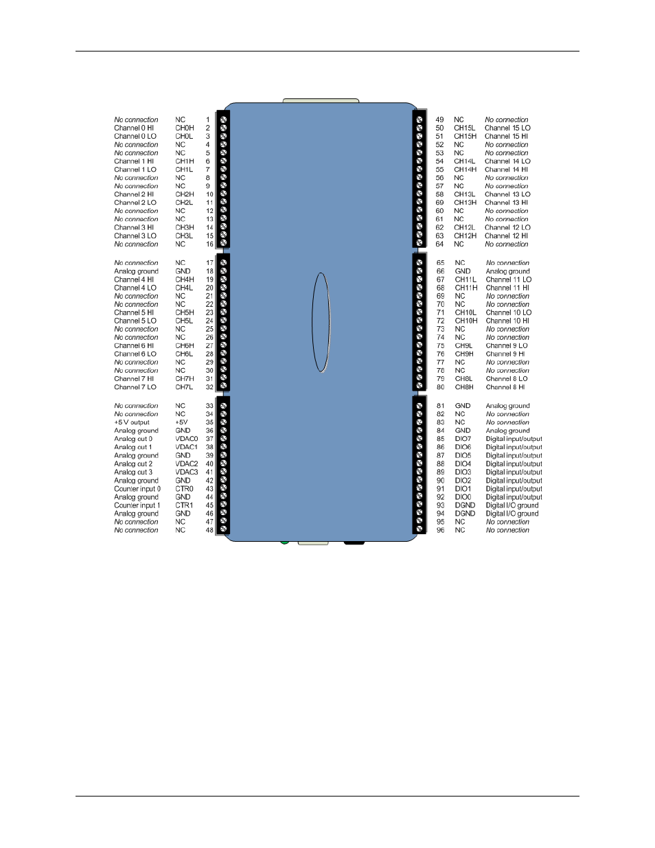
Screw terminal pin out – differential
Figure 4. 16-channel differential mode pin out
Differential connection guidelines
When connecting differential voltage inputs to a "floating" voltage source, make sure there is a DC return
path from each voltage input to ground. You make this path by connecting a resistor from each input to a
GND pin (pins 18, 36, 39, 42, 44, 46, 66, 81, 84). A value of approximately 100 k
Ω can be used for most
applications.
Leave unused input channels either floating or tied to GND (pins 18, 36, 39, 42, 44, 46, 66, 81, 84).
Source impedances should be kept as small as possible to avoid settling time and accuracy errors.
When configuring thermocouple sensors, keep any stray capacitance as small as possible relative to GND
(pins 18, 36, 39, 42, 44, 46, 66, 81, 84) to avoid settling time and accuracy errors. For thermocouple
channels, do not provide a return path to ground. This is done internally.