External pull-up/pull-down capability, Counter input terminals (ctr0, ctr1) – Measurement Computing USB-2416 User Manual
Page 19
USB-2416 User's Guide
Functional Details
19
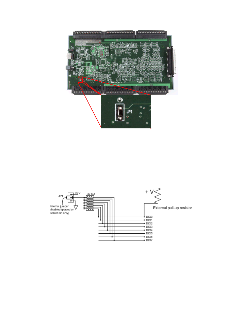
Figure 15. Location of JP1
The pull-up/pull-down voltage is common to all of the internal 47
kΩ resistors.
External pull-up/pull-down capability
You can also place an external pull-up resistor on any of the DIO bits. This enables you to pull the DIO bit up to
a voltage that exceeds the internal +5 V pull-up voltage.
When using external pull-up resistors, note the following:
You should either remove the JP1 jumper or store it by attaching it to one of the three pins.
When using external pull-up resistors, the internal resistors cause slight impedance shifts to digital lines in
the "on" state as the number of lines in the "off" state changes.
Figure 16. Digital I/O external resistor configuration
Counter input terminals (CTR0, CTR1)
Two 32-bit event counters are built into the USB-2416. Each counter accepts frequency inputs up to 1 MHz.
Refer to the Screw terminal pinout diagrams starting on page 10 for the location of these pins. The internal
counter increments when the TTL levels transition from low to high. The counter can count frequencies of up to
1 MHz.