Signal i/o connectors, Bnc connectors, Auxiliary connector – Measurement Computing USB-2020 User Manual
Page 23
USB-2020 User's Guide
Specifications
Signal I/O connectors
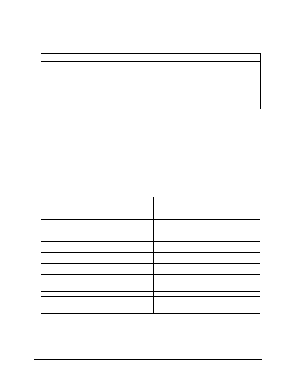
Table 13. Connector specifications
Connector
Specification
USB
B type
Auxiliary connector (J9)
40-pin header connector
Compatible cables for the 40-pin
auxiliary connector
C40FF-x
C40-37F-x
Compatible accessory products with
the C40FF-x cable
CIO-MINI40
Compatible accessory products with
the C40-37F-x cable
CIO-MINI37
SCB-37
BNC connectors
Table 14. BNC connector pinout
BNC signal name
Signal description
CH0
Analog input channel 0
CH1
Analog input channel 1
TRIG IN
BNC connection for external digital trigger (Note 4)
CLK IO
BNC connection for the ADC clock input/output, software-selectable for input or
output (default is input)
Note 4:
Also available on the auxiliary connector J9.
Auxiliary connector
Table 15. 40-pin connector J9 pinout
Pin
Signal name
Pin description
Pin
Signal name
Pin description
1
GND
Ground
2
+VO
Power output
3
GND
Ground
4
N/C
Do not connect
5
DIO7
Digital I/O bit 7
6
N/C
Do not connect
7
DIO6
Digital I/O bit 6
8
N/C
Do not connect
9
DIO5
Digital I/O bit 5
10
TRIG IN
External digital trigger input
11
DIO4
Digital I/O bit 4
12
GND
Ground
13
DIO3
Digital I/O bit 3
14
GND
Ground
15
DIO2
Digital I/O bit 2
16
GND
Ground
17
DIO1
Digital I/O bit 1
18
GND
Ground
19
DIO0
Digital I/O bit 0
20
GND
Ground
21
GND
Ground
22
N/C
Do not connect
23
N/C
Do not connect
24
N/C
Do not connect
25
GND
Ground
26
N/C
Do not connect
27
N/C
Do not connect
28
N/C
Do not connect
29
GND
Ground
30
N/C
Do not connect
31
N/C
Do not connect
32
N/C
Do not connect
33
GND
Ground
34
N/C
Do not connect
35
+VO
Power output
36
N/C
Do not connect
37
GND
Ground
38
N/C
Do not connect
39
N/C
Do not connect
40
N/C
Do not connect
Note 5:
N/C = no connection, not used
23