Connectors and leds, Bnc connectors, Status leds – Measurement Computing USB-2020 User Manual
Page 12: Usb connector, External power connector
USB-2020 User's Guide
Functional Details
Connectors and LEDs
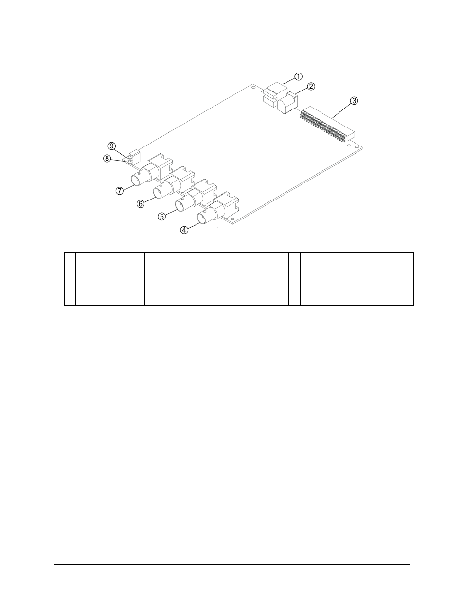
Figure 4. Location of connectors and LEDs
1 USB connector
4 Clock I/O BNC connector (CLK IO)
7 Analog input channel 0 BNC
connector (CH0)
2 External power
connector
5 External digital trigger input BNC connector
(TRIG IN)
8 USB Activity LED
3 40-pin IDC connector 6 Analog input channel 1 BNC connector
(CH1)
9 Device Ready LED
BNC connectors
The USB-2020 has four BNC connectors that provide connections for the following signals:
Two single-ended analog inputs
One external digital trigger input
One clock input/output
The external digital trigger input signal is also available on the 40-pin IDC connector.
Status LEDs
The
Device Ready
LED turns on after the device is enumerated by the system and is associated with a
hardware driver.
The
USB Activity
LED turns on when the USB-2020 is transmitting or receiving data.
USB connector
The USB connector provides power to the USB-2020 and communication with the host computer.
External power connector
The USB-2020 requires external power. Connect the CB-PWR-9 power supply to the external power connector.
This power supply provides 9 VDC, 3 A power, and plugs into a standard 120 VAC outlet.
12