External trigger, External clock input/output, Memory – Measurement Computing USB-2020 User Manual
Page 21: External, Trigger, Clock input/output
USB-2020 User's Guide
Specifications
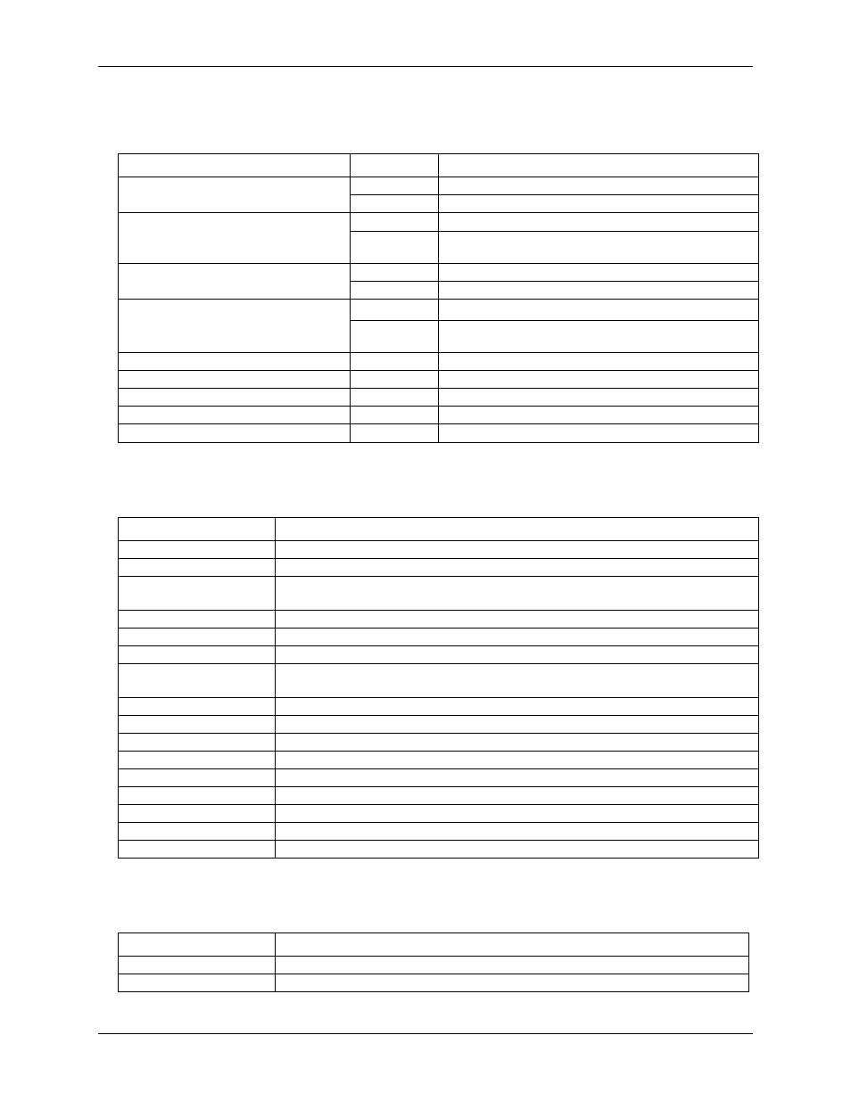
External trigger
Table 6. External trigger specifications
Parameter
Condition
Specification
Trigger source
Digital
TRIG IN (BNC connector and 40-pin connector)
Analog
CH0 or CH1
Trigger mode
Digital
Rising or falling edge, high or low level
Analog
Trigger above or below software-selectable level, rising or
falling edge with software-selectable hysteresis
A/D gate source
Digital
TRIG IN (BNC connector and 40-pin connector)
Analog
CH0 or CH1
A/D gate modes
Digital
High or low level
Analog
Software-selectable high or low level, in or out of software-
selectable window
Trigger latency
50 ns max
Trigger pulse width
25 ns min
Input type
49.9 Ω series resistor
Input high voltage
2.0 V min
Input low voltage
0.8 V max
External clock input/output
Table 7. External clock I/O specifications
Parameter
Specification
Terminal name
CLK IO (BNC connector)
Terminal type
ADC clock input/output, software-selectable for input or output (default is input)
Terminal description
When configured for input, receives sampling clock from external source
When configured for output, outputs the internal sampling clock
Clock rate
1 kHz to 20 MHz max
Stability
±50 ppm
Input impedance
1 MΩ
Input threshold
High: 2.0 V min
Low: 0.8 V max
Maximum rate
20 MHz
Input range
0 V to 5.5 V
Clock pulse width
25 ns min
Input type
49.9 Ω series resistor
Input high voltage
2.0 V min
Input low voltage
0.8 V max
Output high voltage
2.4 V min
Output low voltage
0.4 V max
Output current
24 mA max
Memory
Table 8. Memory specifications
Parameter
Specification
Data FIFO
64 MS using BURSTIO, 4 kS not using BURSTIO
Non-volatile memory
32 KB (30 KB firmware storage, 2 KB calibration/user data)
21