External clock i/o, Digital i/o, External pull-up capability – Measurement Computing USB-2020 User Manual
Page 15: Buffer, Size limitations on windows systems
USB-2020 User's Guide
Functional Details
Buffer size limitations on Windows systems
When creating very large buffers in Windows, you may receive the message
The requested amount of
Windows page-locked memory is not available
when you try to start a scan. This error occurs when there is
enough memory to create the buffer, but the memory cannot be locked down. For example, the driver can only
lock a maximum buffer size of 67,107,800 bytes (33,553,900 samples) on Windows XP systems. A workaround
for this is available when BURSTIO is enabled, allowing you to transfer the entire 64 MS of data from the
onboard memory to the Windows buffer. For more information, refer to the USB-2020 topic (Hardware
Considerations
section) in the Universal Library Help (User's Guide section).
You can pace analog input operations with the internal A/D clock or with an external clock source. When using
an external input scan clock, connect the clock source to the
CLK IO
BNC connector.
External clock I/O
USB-2020 analog input scanning operations can be paced with the internal A/D clock or with an external clock
source.
The CLK IO connector can be configured through software for input (default) for external pacing, or for output
to pace a connected device.
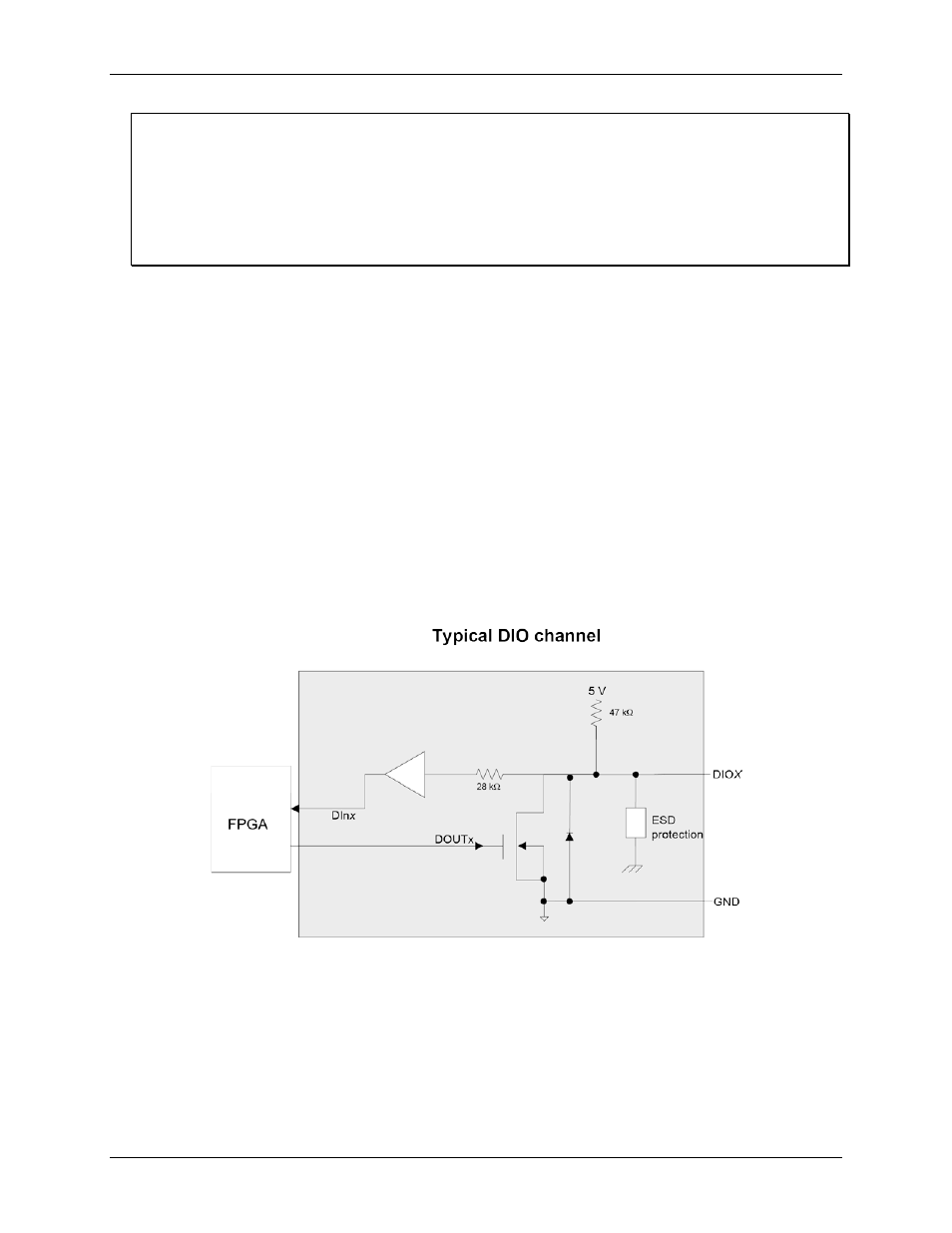
Digital I/O
You can connect up to eight digital I/O lines to DIO0 through DIO7 on the 40-pin IDC connector. When a bit is
configured for input, it can detect the state of any TTL-level input.
Digital input voltage ranges of up to 0 to 15 V are permitted, with thresholds of 0.8 V (low) and 2.0 V (high).
Each DIO channel is an open-drain, which can sink up to 150 mA for direct drive applications when used as an
output.
Figure 6 shows an example of a typical digital output connection.
Figure 5. Digital output connection
External pull-up capability
Inputs are pulled high by default to 5 V through 47 kΩ resistors on the circuit board. The pull-up voltage is
common to all 47 kΩ resistors.
You can configure the pull-up/pull-down state by changing the placement of the shorting block located at the
three-pin header J10. Pull-up is the default factory configuration
15