Led displays and the factory reset button, Environmental, Mechanical – Measurement Computing E-1608-OEM User Manual
Page 26: Header connectors
26
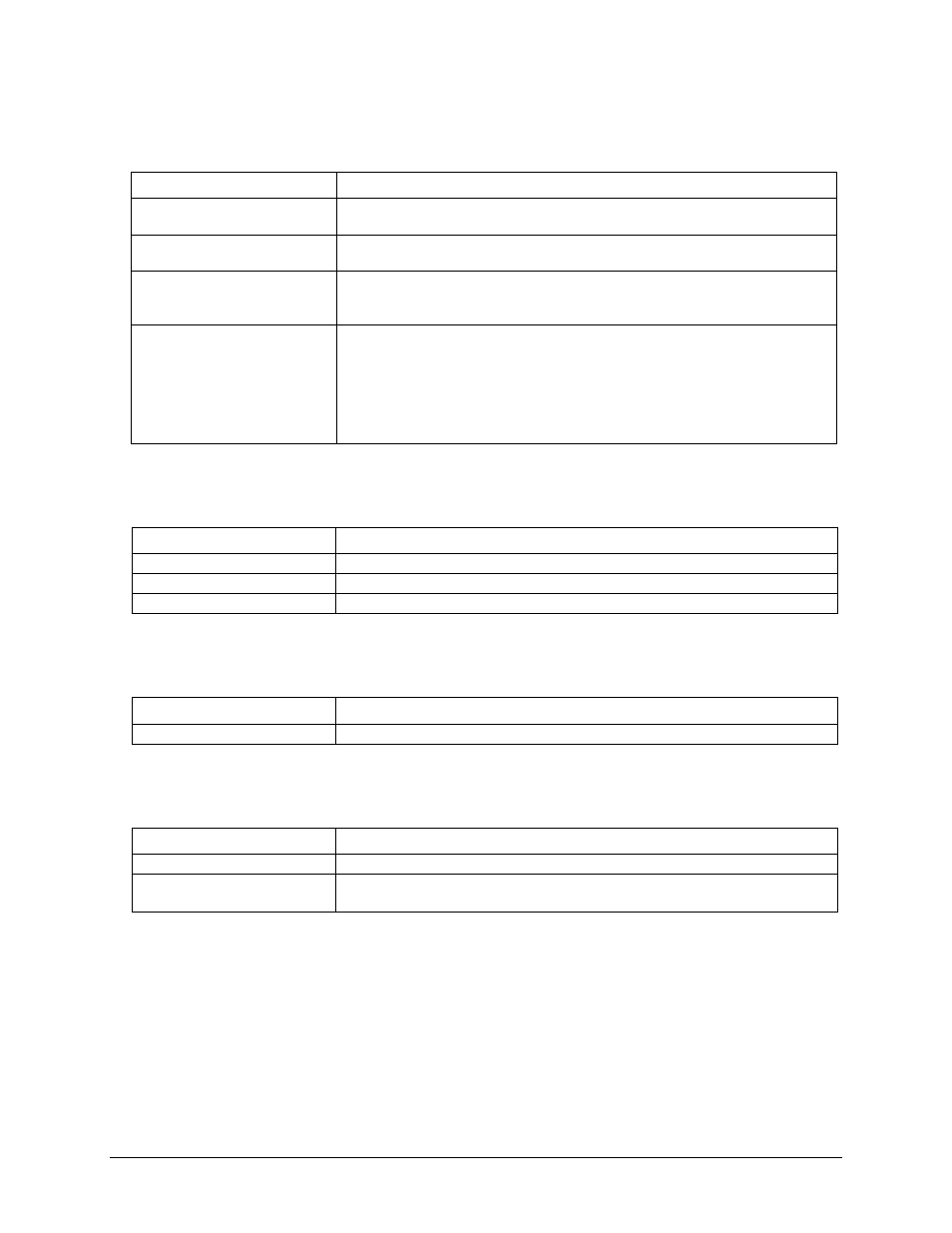
LED displays and the factory reset button
Table 20. LED and button configurations
Parameter
Specification
Power LED (top)
3.3 V < V
ext
< 5.9 V: On
V
ext
< 3.3 V
,
V
ext
> 5.9 V: Off (power fault)
Activity LED (bottom)
On when there is a valid host connection and blinks when a command is received or
an AInScan is running.
Ethernet connector LEDS
Left (green): Link/activity indicator; on when there is a valid Ethernet link and
blinks when network activity is detected.
Right (yellow): Speed indicator; on for 100 Mbps, off for 10 Mbps or no link.
Factory reset button
Used to reset the network configuration settings to the factory default values.
Press the button when applying power to the device and continue to hold for
4 seconds; the device LEDs stay off, and then both the Power and Activity LEDs
blink once indicating that the settings have been restored to the defaults.
Release the button so the device continues startup with the default settings. If the
button is released before the two LEDs blink, the settings are not affected and the
device starts up normally.
Environmental
Table 21. Environmental specifications
Parameter
Specification
Operating temperature range
0 °C to 55 °C max
Storage temperature range
–40 °C to 85 °C max
Humidity
0% to 90% non-condensing max
Mechanical
Table 22. Mechanical specifications
Parameter
Specification
Dimensions (L × W × H)
96.27 × 76.71 × 14.61 mm (3.79 × 3.02 × 0.575 in.) max
Header connectors
Table 23. Header connector specifications
Parameter
Specification
I/O connector type
Two 2 × 8 pin 0.1 in. pitch headers labeled W2 and W4
Power connector type
DC barrel input jack labeled J4 (mates with 5.5mm OD / 2.1 mm ID plug) and
1 x 2 pin 0.1 in. pitch header labeled W1