Connector w2, Connector w4, Screw terminal connectors – Measurement Computing E-1608-OEM User Manual
Page 14: Signal connections, Analog input, Floating voltage source
E-1608-OEM User's Guide
Functional Details
14
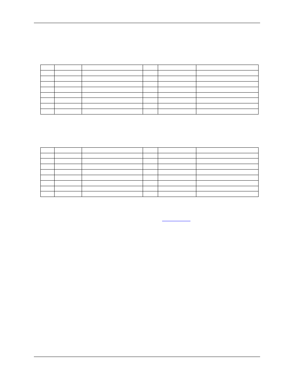
Connector W2
Header connector W2 provides connections for the DIO, external clock I/O, trigger, counter, power output, and
digital ground reference.
W2 pinout
Pin
Signal name
Pin description
Pin
Signal name
Pin description
1
DIO0
DIO channel 0
2
DIO1
DIO channel 1
3
DIO2
DIO channel 2
4
DIO3
DIO channel 3
5
DIO4
DIO channel 4
6
DIO5
DIO channel 5
7
DIO6
DIO channel 6
8
DIO7
DIO channel 7
9
GND
Digital ground
10
+VO
User voltage output
11
GND
Digital ground
12
AICKO
External clock pacer output
13
AICKI
External clock pacer input
14
CTR
Counter input
15
TRIG
Digital trigger input
16
GND
Digital ground
Connector W4
Header connector W4 provides connections for the analog inputs, analog outputs, and the analog ground
reference.
W4 pinout
Pin
Signal name
Pin description
Pin
Signal name
Pin description
1
CH0H
Channel 0 high (SE channel 0)
2
CH0L
Channel 0 low (SE channel 1)
3
AGND
Analog ground
4
CH1H
Channel 1 high (SE channel 2)
5
CH1L
Channel 1 low (SE channel 3)
6
AGND
Analog ground
7
CH2H
Channel 2 high (SE channel 4)
8
CH2L
Channel 2 low (SE channel 5)
9
AGND
Analog ground
10
CH3H
Channel 3 high (SE channel 6)
11
CH3L
Channel 3 low (SE channel 7)
12
AGND
Analog ground
13
AOUT0
Analog output 0
14
AGND
Analog ground
15
AOUT1
Analog output 1
16
AGND
Analog ground
Screw terminal connectors
Screw terminals J1 through J3 and J7 through J9 are unpopulated. When populated, the screw terminals provide
alternative connections to the header connectors. Refer to the
chapter for screw terminal pinouts.
Signal connections
Analog input
You can configure the analog inputs for SE or DIFF mode. The input voltage range is software selectable for
±10 V, ±5 V, ±2 V, or ±1 V.
With SE mode, connect up to eight inputs to
CH0x
to
CH3x
. SE mode requires two wires:
Connect one wire to the signal you want to measure (
CH#x
).
Connect one wire to the analog ground reference (
AGND
).
With DIFF mode, connect up to four differential inputs to
CH0H/CH0L
to
CH3H/CH3L
. DIFF mode requires
two wires plus a ground reference:
Connect one wire to the high/positive signal (
CHxH
).
Connect one wire to the low/negative signal (
CHxL
).
Connect one wire to the analog ground reference (
AGND
).
Floating voltage source
When connecting DIFF voltage inputs to a floating voltage source, make sure the DIFF input channel has a DC
return path to ground. To create this path, connect a resistor from each low channel input to an AGND pin. A
value of approximately 100 kΩ can be used for most applications.