Channel-gain queue, Analog output – Measurement Computing E-1608-OEM User Manual
Page 15
E-1608-OEM User's Guide
Functional Details
15
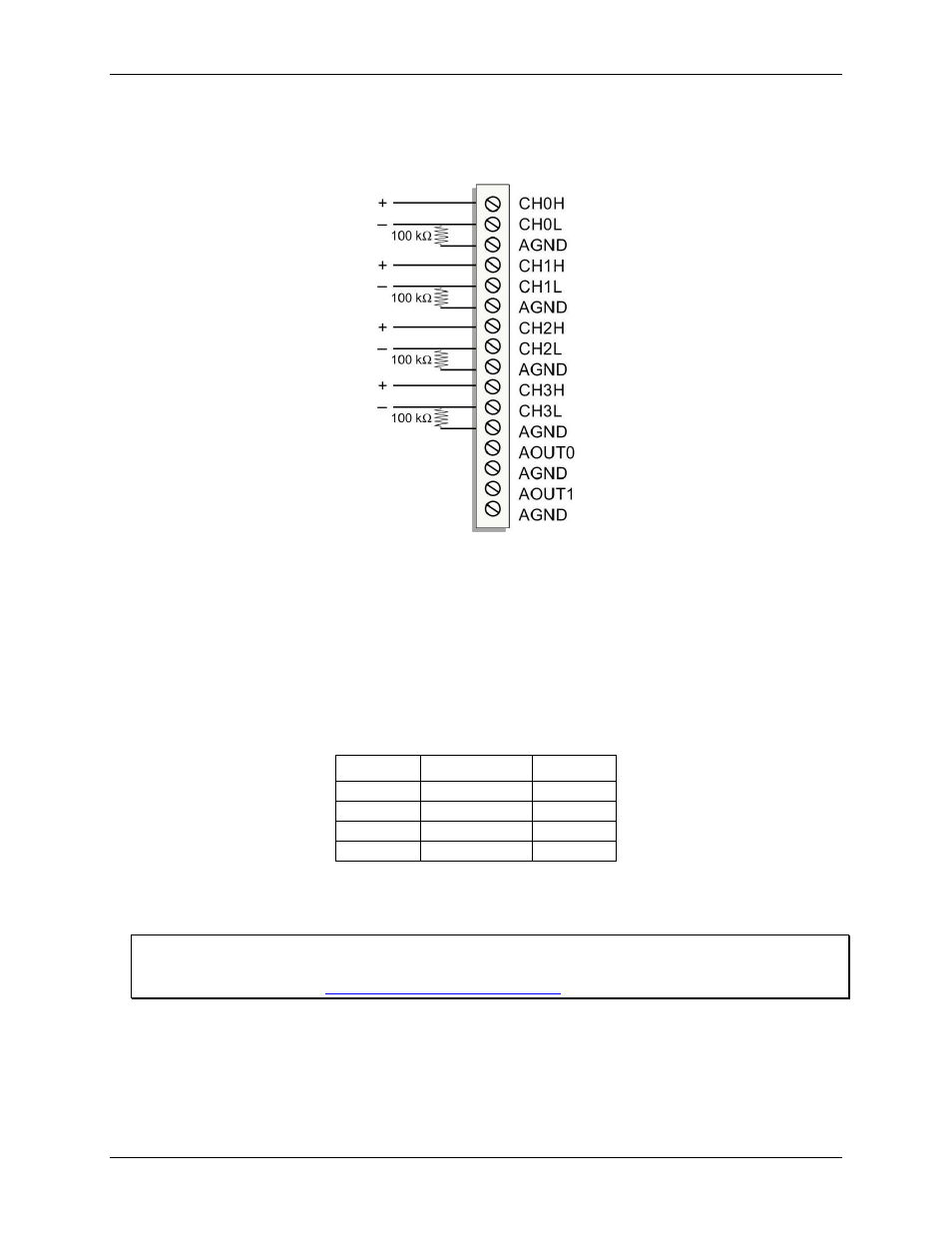
Leave unused input channels either floating or tied to an AGND connector. Source impedances should be kept
as small as possible to avoid settling time and accuracy errors.
Figure 3 shows DIFF channels 0-3 connected to a ground path resistor.
Figure 3. DIFF connections with ground path resistor
Channel-Gain queue
The channel-gain queue feature allows you to configure a list of channels, modes, and gains for each scan. The
settings are stored in a channel-gain queue list that is written to local memory on the device.
The channel-gain queue list contains one or more channel numbers, modes, and range settings. You can
configure up to 8 elements. The channels can be listed in any order, and can include duplicate channels for
sampling at different ranges.
An example of a 4-element list is shown in the table below.
Sample channel gain queue list (SE mode)
Element
Channel
Range
0
CH5
BIP5V
1
CH1
BIP10V
2
CH3
BIP1V
3
CH5
BIP5V
Carefully match the gain to the expected voltage range on the associated channel or an over range condition
may occur. Although this condition does not damage the device, it does produce a useless full-scale reading,
and can introduce a long recovery time due to saturation of the input channel.
For more information about analog signal connections
For more information about analog input connections, refer to the Guide to Signal Connections (this document
is available on our website
Analog output
Two 16-bit analog outputs are available at AOUT0 and AOUT1.
Each analog output channel has an output range of ±10 V. Throughput is system-dependent.
The D/A is software-paced. Each 16-bit analog output (
AOUT0
and
AOUT1
) can be updated simultaneously at
rates from 1000 S/s to 5000 S/s. This is the typical throughput when the device and host are both connected by