Cio-pdiso8 compatibility – Measurement Computing CIO-PDISO16 User Manual
Page 13
CIO-PDISO16 User's Guide
Installing the CIO-PDISO16
12
Do not use exposed-screw terminal boards if your field voltage is more than 24 volts. Using a screw terminal
board with high voltage inputs or outputs exposes you and others to those high voltage signals. Construct a safe
cable to carry your signals directly from your equipment to the CIO-PDISO16 connector.
Caution! High voltages are present on the CIO-PDISO16 when you have connected high voltage inputs or
outputs to the CIO-PDISO16 connector. Use extreme caution! Never handle the CIO-PDISO16
when signals are connected to the board through the connector.
Never remove the protective plates from the CIO-PDISO16.
CIO-PDISO8 compatibility
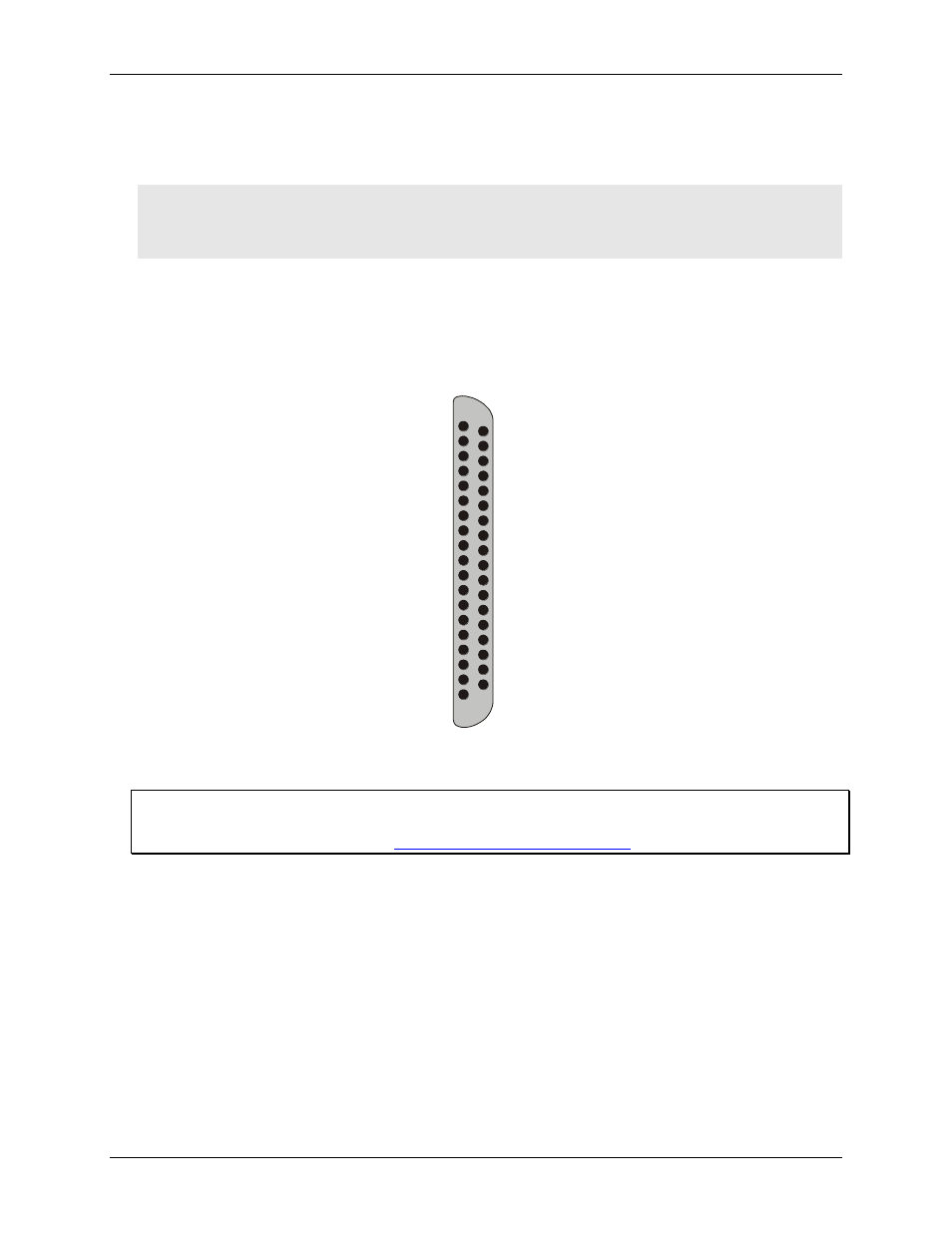
The C50-37F-x cable converts the CIO-PDISO16 to a CIO-PDISO8 compatible D-type connector. The
C50-37F-x cable has a 50-pin header connector at one end and a 37-pin female D-sub connector at the other
end.
RELAY 0 (NO) 19
18
17
16
15
14
13
12
11
10
9
INPUT 0 8
7
6
5
4
3
2
1
RELAY 0 (NC)
RELAY 1 (C)
RELAY 2 (NO)
RELAY 2 (NC)
RELAY 3 (C)
RELAY 4 (NO)
RELAY 4 (NC)
RELAY 5 (C)
RELAY 6 (C)
RELAY 7 (C)
INPUT 1
INPUT 2
INPUT 3
INPUT 4
INPUT 5
INPUT 6
INPUT 7
37 RELAY 0 (C)
36
35
34
33
32
31
30
29
28
27 INPUT 0
26
25
24
23
22
21
20
RELAY 1 (NO)
RELAY 1 (NC)
RELAY 2 (C)
RELAY 3 (NO)
RELAY 3 (NC)
RELAY 4 (C)
RELAY 5 (NO)
RELAY 6 (NO)
RELAY 7 (NO)
INPUT 1
INPUT 2
INPUT 3
INPUT 4
INPUT 5
INPUT 6
INPUT 7
(NO) = Normally Open, (C) = Common, (NC) = Normally Closed.
C50-37F-x cable pin out
For additional information about digital interfacing
Detailed information regarding digital interfacing is contained in MCC's Guide to Signal Connections. This
document is available on our web sit