Pin out – 50-pin i/o connectors, Cabling, Field wiring and signal termination accessories – Measurement Computing CIO-PDISO16 User Manual
Page 12: Field wiring, signal, Termination and conditioning, Ge 11
CIO-PDISO16 User's Guide
Installing the CIO-PDISO16
11
Information on signal connections
General information regarding signal connection and configuration is available in the Guide to Signal
Connections. This document is available on our web sit
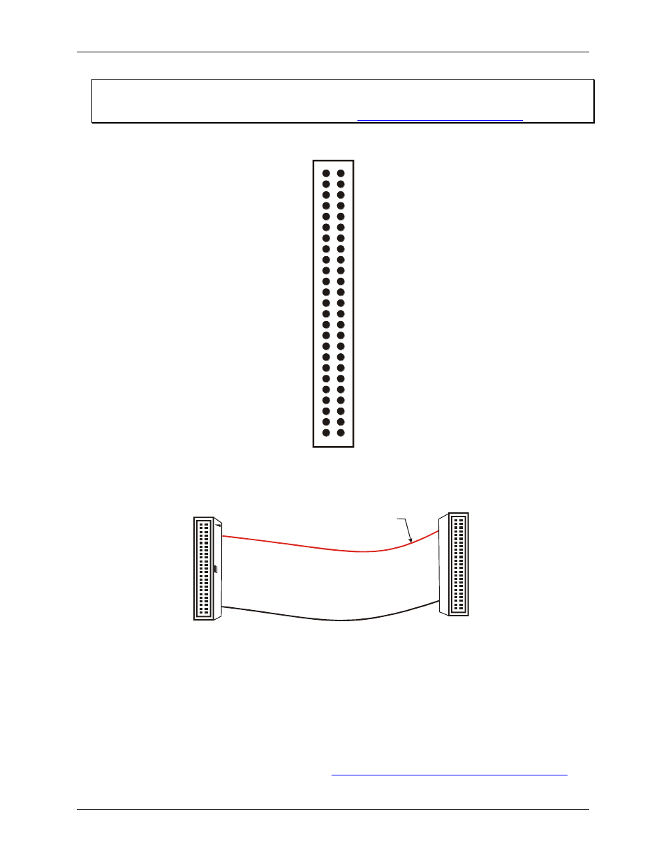
Pin out
– 50-pin I/O connectors
NC 50
48
46
44
42
RELAY 6 (NC) 40
38
36
34
32
30
28
26
24
22
20
18
INPUT 0 16
14
12
10
8
6
4
2
NC
NC
NC
NC
RELAY 7 (NC)
RELAY 0 (C)
RELAY 1 (NO)
RELAY 1 (NC)
RELAY 2 (C)
RELAY 3 (NO)
RELAY 3 (NC)
RELAY 4 (C)
RELAY 5 (NO)
RELAY 6 (NO)
RELAY 7 (NO)
INPUT 1
INPUT 2
INPUT 3
INPUT 4
INPUT 5
INPUT 6
INPUT 7
49 NC
47
45
43
41
39 RELAY 5 (NC)
37
35
33
31
29
27
25
23
21
19
17
15 INPUT 0
13
11
9
7
5
3
1
NC
NC
NC
NC
RELAY 0 (NO)
RELAY 0 (NC)
RELAY 1 (C)
RELAY 2 (NO)
RELAY 2 (NC)
RELAY 3 (C)
RELAY 4 (NO)
RELAY 4 (NC)
RELAY 5 (C)
RELAY 6 (C)
RELAY 7 (C)
INPUT 1
INPUT 2
INPUT 3
INPUT 4
INPUT 5
INPUT 6
INPUT 7
50-pin header connector pin out
Cabling
The red stripe
identifies pin # 1
50-pin Female
IDC connector
50-pin Female
IDC Connector
1
2
49
50
2
50
1
49
Figure 5. C50FF-x cable
Field wiring and signal termination accessories
You can connect the CIO-PDISO16 to the following accessory board using the C50FF-x cable.
CIO-MINI50 – Universal screw terminal board, 50-pin.
Details on this product is available on our web sit