Relay screw terminals, Relay logic jumper (jp2), Power-in jumper (jp1) – Measurement Computing 6K-ERB08 User Manual
Page 26: Relays pull-up/down option, Relay screw terminals -2, Relay logic jumper (jp2) -2, Power-in jumper (jp1) -2, Relays pull-up/down option -2
6K-ERB08 User's Guide
Specifications
Relay screw terminals
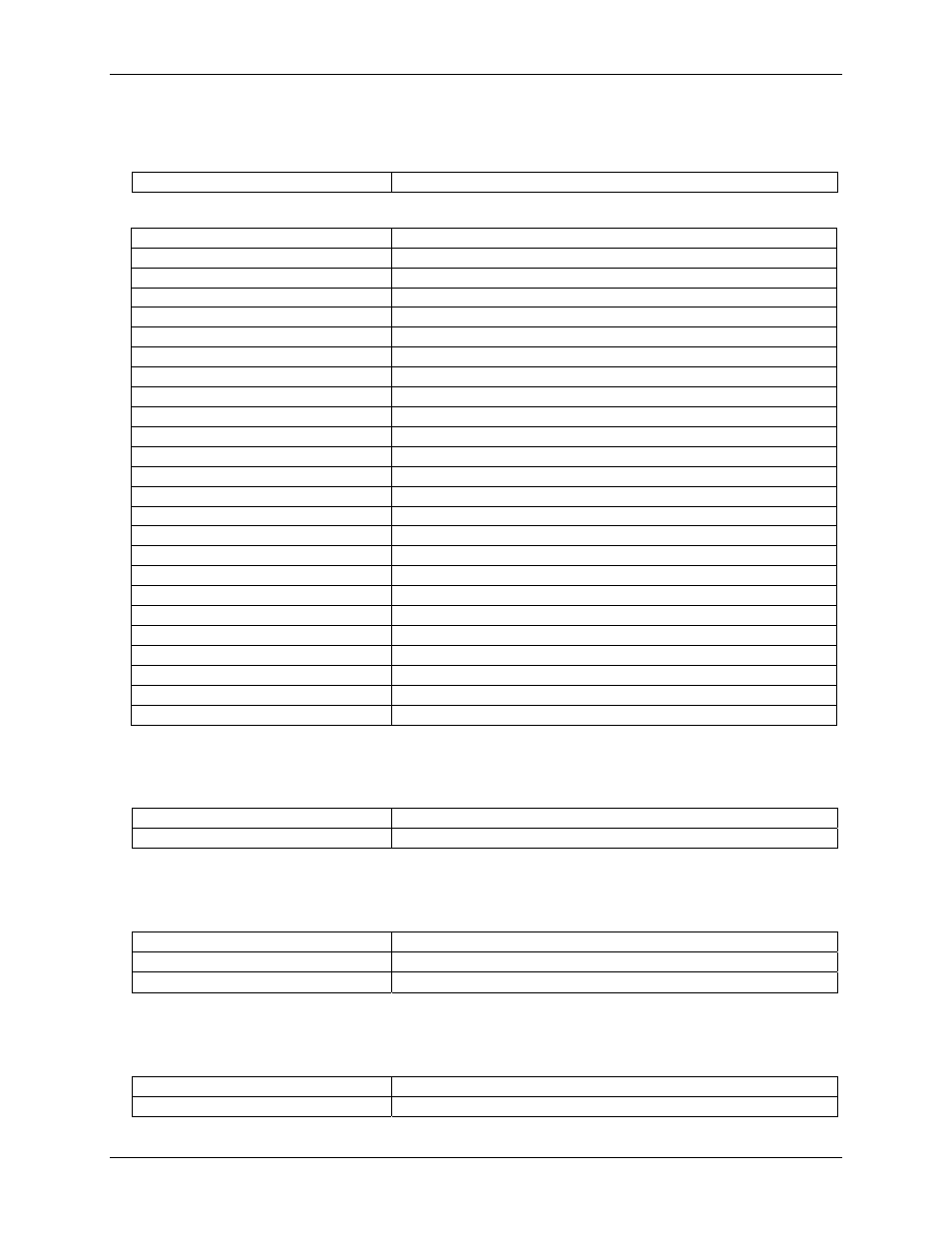
Table 5. Relay screw terminal specifications
Wire gauge range
12 AWG to 20 AWG
Table 6. Screw terminal pin out
Pin Signal
Name
1-NO
Relay 1 Normally Open contact
1-C
Relay 1 Common contact
1-NC
Relay 1 Normally Closed contact
2-NO
Relay 2 Normally Open contact
2-C
Relay 2 Common contact
2-NC
Relay 2 Normally Closed contact
3-NO
Relay 3 Normally Open contact
3-C
Relay 3 Common contact
3-NC
Relay 3 Normally Closed contact
4-NO
Relay 4 Normally Open contact
4-C
Relay 4 Common contact
4-NC
Relay 4 Normally Closed contact
5-NO
Relay 5 Normally Open contact
5-C
Relay 5 Common contact
5-NC
Relay 5 Normally Closed contact
6-NO
Relay 6 Normally Open contact
6-C
Relay 6 Common contact
6-NC
Relay 6 Normally Closed contact
7-NO
Relay 7 Normally Open contact
7-C
Relay 7 Common contact
7-NC
Relay 7 Normally Closed contact
8-NO
Relay 8 Normally Open contact
8-C
Relay 8 Common contact
8-NC
Relay 8 Normally Closed contact
Relay logic jumper (JP2)
Table 7. JP2 specifications
Invert (1-2)
Relay activates when DIO is LOW
Non-invert (2-3) (default)
Relay activates when DIO is HIGH
Power-in jumper (JP1)
Table 8. JP1 specifications
+5PC
Use cable C-PCPOWER-10
+9V EXT
Use Adapter CB-PWR-9
+5BD (default)
Powered from 100-pin connector
Relays pull-up/down option
Table 9. Relay pull-up/down specifications
R21,23,25,27,29,31,33,35
Relays NC pin pull-up/down
R20,22,24,26,28,30,32,34
Relays NO pin pull-up/down
4-2