Power source, External +5 v pc power connections, Power source -9 – Measurement Computing 6K-ERB08 User Manual
Page 18: Figure 2-4
6K-ERB08 User's Guide
Installing the 6K-ERB08
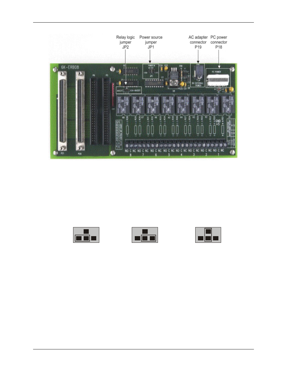
Figure 2-4. 6K-ERB08 board jumpers and external power connectors
Power source
Set the power source with jumper
JP1
(labeled
POWER IN
). You can power the 6K-ERB08 using one of the
following sources.
The 6000 Series control board’s internal +5 V power supply (default)
Your computer’s +5 V power supply, or external +5 V supply (power cable supplied)
AC adapter (supplied)
Figure 2-5. Power source jumper JP1configurations
POWER
IN
jumper setting for each power source.
+5BD
Internal power
from the MCC board
External power from
the computer’s power supply
+5PC
External power from
an AC adapter
9V EXT
Internal power
from the MCC board
External power from
the computer’s power supply
External power from
an AC adapter
External +5 V PC power connections
You can power the 6K-ERB08 with your computer’s +5 V power supply using the
C-PCPOWER-10
cord that
was shipped with the board. Each end of the cable has a keyed MOLEX type connector. To connect to your
computer’s internal power connectors, do the following:
1.
2.
3.
4.
5.
Turn your computer off, remove the cover, and insert your board into an available PCI slot.
Close your computer and turn it on.
Turn off power to the computer and remove the cover.
Connect one end of the C-PCPOWER10 power cord to one of your computer’s internal power connectors.
If necessary, refer to your computer's user manual for the location of the power supply connectors.
Run the power cable out the back of the computer through an expansion slot or other opening, and replace
the cover on the computer.
2-9