Screw terminal connections, Wire gauge, Power up conditions – Measurement Computing 6K-ERB08 User Manual
Page 22: Screw terminal connections -3, Wire gauge -3, Power up conditions -3
6K-ERB08 User's Guide
Functional Details
Screw terminal connections
Connect external devices to the relay contacts using the 6K-ERB08 screw terminals. Each relay has a common
(C), normally closed (NC), and normally open (NO) contact.
shows the screw terminals on a typical
relay channel.
Figure 3-3. Typical relay channel
NO C NC
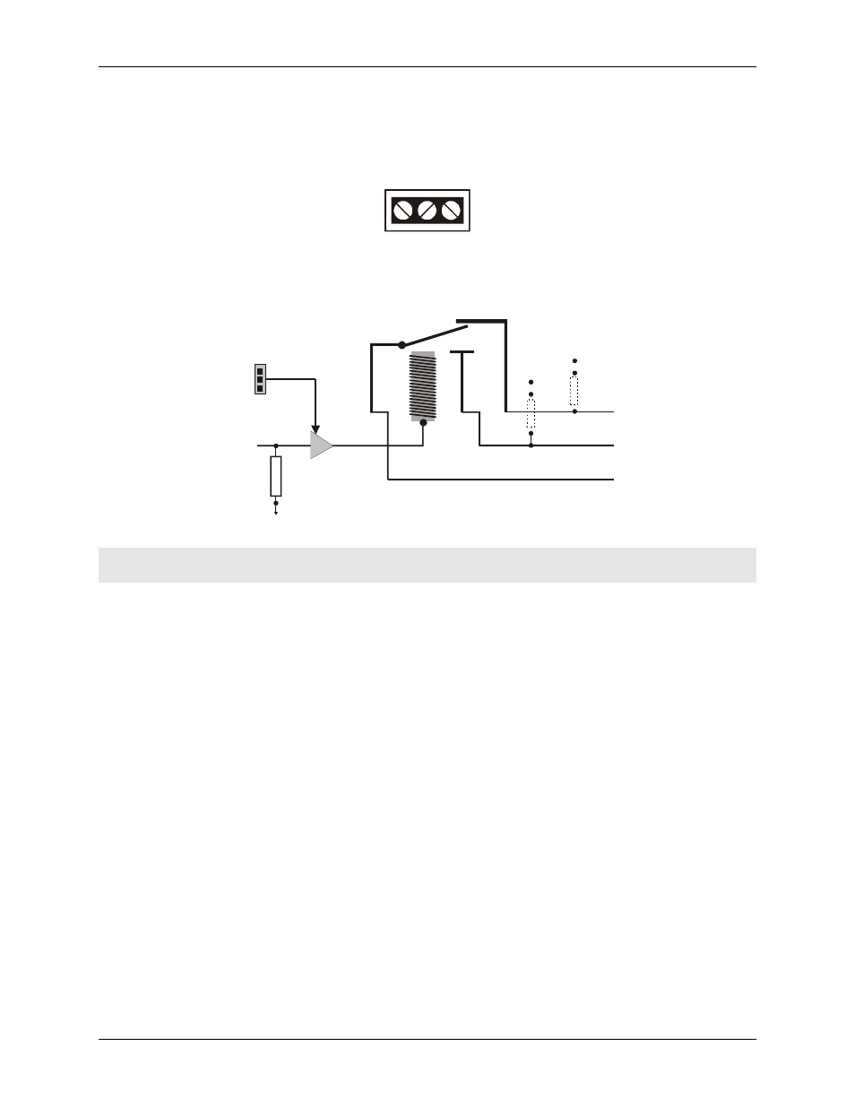
The relay configuration is illustrated in Figure 3-4. You can install a pull-up or pull-down resistor at the NO and
NC terminals on each relay.
User-installed
pull-up / pull-down resistor
GND
+5
Screw
terminals
(3 per
relay)
GND
+5
C
NO
NC
Digital output
from the
MCC board
Buffer/
driver
10 k
pull-down
resistor
Invert
Non-Invert
Logic
jumper
Figure 3-4. Relay configuration
Caution!
Before connecting signal wires to the relay screw terminals, turn off the power to the 6K-ERB08,
and make sure that the signal wires do not contain live voltages.
Wire gauge
Use 12 AWG to 20 AWG wire to connect field devices. Properly insulate the wires to avoid any short circuit to
the other connections, ground, or other points on the board.
Power up conditions
The state of the relay modules at power up depends on both the state of the digital signals controlling them and
the relay logic jumper setting.
When you set the relay logic jumper to
NON-INVERT
, the C and NC contacts are connected when the 6K-
ERB08 is disconnected from the 6000 Series control board or when the digital lines on the 6000 Series
control board are in high impedance (or input) mode.
When you set the relay logic jumper to
INVERT
, the C and NO contacts are connected when the 6K-ERB08
is disconnected from the 6000 Series control board, or when the digital lines on the 6000 Series control
board are in high impedance (or input) mode.
3-3