Connectors, cables – interface i/o connectors, Connectors, cables – interface i/o connectors -3 – Measurement Computing 6K-ERB08 User Manual
Page 12
6K-ERB08 User's Guide
Installing the 6K-ERB08
Connectors, cables – interface I/O connectors
The 6K-ERB08 board’s eight relays are controlled by your 6000 Series control board’s digital channels through
AUXPORT. Digital channels DIO<0:7> correspond to relays 1 to 8. Connect your signal cable from the
6000 Series control board’s interface connector to one of the interface connectors on the relay board.
The 6K-ERB08 has two 100-pin interface connectors labeled
P21
and
P20
, and two 50-pin interface connectors
labeled
P6
and
P5
. Signals pass through each connector. Only connect one of the four interface connectors to
your 6000 Series control board.
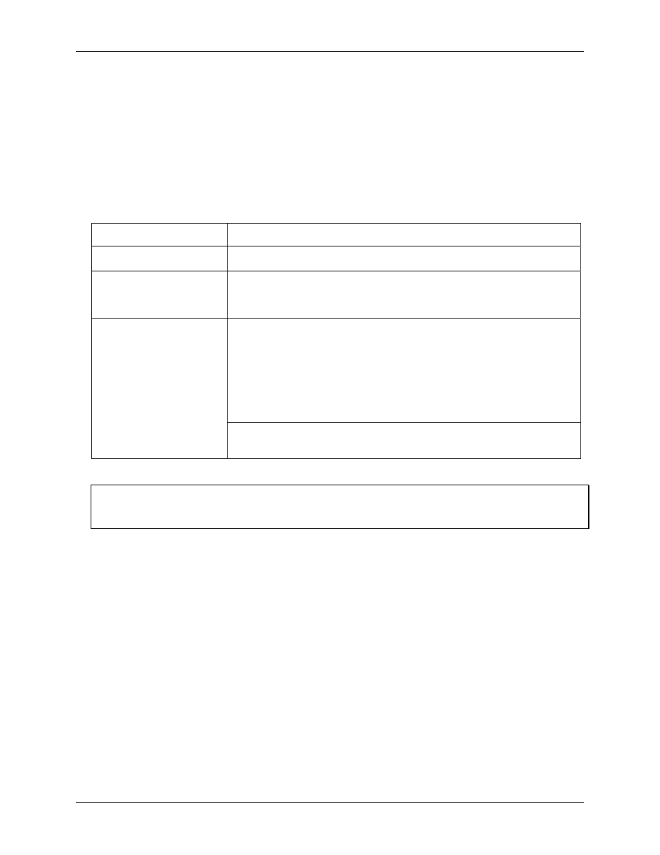
Table 2-1
Table 2-1. Board connectors, cables, and compatible hardware
lists the board connectors, applicable cables, and compatible MCC hardware for the 6K-ERB08.
Connector type
P21 and P20: Shielded, SCSI 100-pin D-type
P6 and P5: Unshielded 50 pin ribbon connector
Compatible cable
(connect to P21 or P20)
C100MMS-x shielded round cable (Figure 2-1). x = 1, 2, or 3 meters
Compatible cable
(connect to P6 or P5)
C100HD50-x shielded round cable (Figure 2-2). x = 3 or 6 feet
C50FF-x unshielded ribbon cable (Figure 2-3)
x = 1, 2, 3, 4, 5, 10, 15, 20, 25 or 50 feet
Note: These cables do not provide power to the 6K-ERB08. External power is required.
PCI-DAS6000 Series boards:
PCI-DAS6013
PCI-DAS6014
PCI-DAS6030
PCI-DAS6031
PCI-DAS6032
PCI-DAS6033
PCI-DAS6034
PCI-DAS6035
PCI-DAS6036
PCI-DAS6052
PCI-DAS6023
PCI-DAS6025
PCI-DAS6040
PCI-DAS6070
PCI-DAS6071
Compatible MCC hardware
PCI-DAC6700 Series analog output boards:
PCI-DAC6702
PCI-DAC6703
Daisy chaining to other 6K-ERB08 boards
Do not daisy chain additional 6K-ERB08 boards to the extra interface connectors, since any additional boards
would be controlled with the same DIO lines.
2-3