Components, Components -2 – Measurement Computing 6K-ERB08 User Manual
Page 21
6K-ERB08 User's Guide
Functional Details
Components
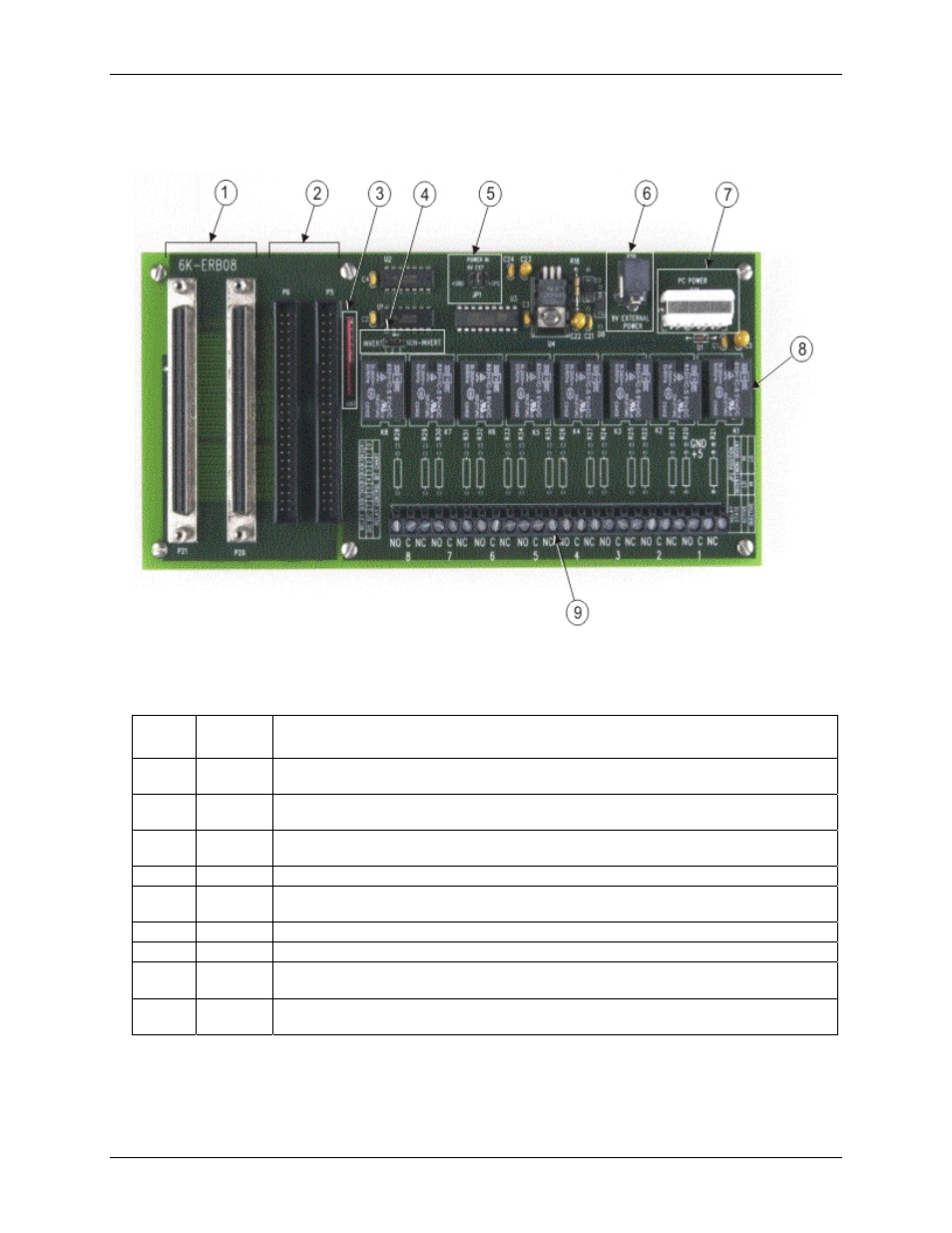
Major components on the 6K-ERB08 are shown in
Figure 3-2. 6K-ERB08 component locations
Table 3-8
Table 3-8. 6K-ERB08 component descriptions
describes the board’s major components.
Callout Board
label
Description
1 P21,
P20
100-pin interface connectors for connecting to the 6000 Series control board or different
accessory boards.
2 P6,
P5
50-pin interface connectors for connecting to the 6000 Series control board or different accessory
boards.
3 RN1 Pull-down resistor to control the state of the relay control lines when not driven by the control
board.
4
JP2
Jumper to configure the relay logic for active high or low.
5 JP1 Main +5 V power jumper to select the power source — internal power from the 6000 Series
control board, external power from the computer, or external power from the AC adapter.
6
P19
External power connector. Connect to the AC adapter.
7
P18
External power connector. Connect to the computer's +5 V supply.
8
K1 to K8
Relays <1:8>. These relays are controlled digitally by the 6000 Series control board's digital bits
DIO<0:7>.
9
1 to 8
Relay screw terminals <1:8>. The screw terminals are for the common (C), normally open (NO)
and normally closed (NC) contacts for relays 1 through 8.
3-2