System description, Mtt-ops-1 – MEGA Corp. MTT-OPS-1 User Manual
Page 15
MTT-OPS-1
13 Nov 2013
SECTION 2
System Description
2-6
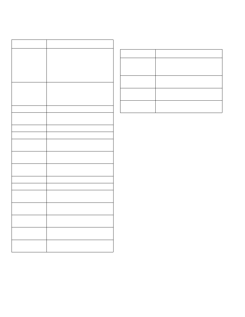
The joystick box functions operate as follows:
BASIC SYSTEM THEORY OF OPERATION
Spray system power is provided by chassis 12/24 volt
DC power. Power is routed to cab controllers and
logic control panels by turning on the switched
power via the ignition key switch.
When the chassis ignition switch is turned ON, the
master switch box will undergo a functional self-test.
During this process, ALL LEDs will first turn ON, then
off. While this is occurring, the water level indicator
lights will initially register a FULL tank, and will then
decrease down to EMPTY. The EMPTY light will blink,
and then the water level indicator will count up to
register the current water level of the tank.
Cab control power is then activated by turning the
cab control POWER switch ON while logic controllers
are switched on when the chassis ignition switch is
turned ON.
The spray system will function normally when cab
control power is applied (cab control POWER switch
ON) and sufficient water (water level EMPTY light not
flashing) is present. Activation of a specific function is
accomplished by depressing the selected function
switch on the master switch box or joystick box.
Depressing the switch sends a signal to the logic
control panel in the solenoid box to activate a given
function. The logic control then receives the signal
and provides an output command to the given coil or
function.
t OFF
(Intermittent
timer—manual
mode)
Sets OFF time between timer
cycles of selected spray heads
when the timer switch is in the
intermittent (INTMNT) position.
Scale: adjustable from 5 seconds
to 30 seconds.
SPEED
(GPS Auto Mode)
Sets desired ground speed for
maximum flow (OPEN continu-
ously) of selected spray heads
(see extended description).
WATER LEVEL
Indicates tank water level.
AUTO
Controls activation of GPS Auto
mode.
AUX 1
Reserved for user-added option.
AUX 2
Reserved for specialized function.
HOSE
Controls activation of hose reel
function ONLY.
SUCTION LOAD
Controls activation of suction
load station ONLY.
LT VSS
Opens or closes left vertical side
spray head.
DRAIN
Opens or closes tank drain BFV.
DUMP BAR
Opens or closes dump bar BFV.
RT VSS
Opens or closes right vertical side
spray head.
LT REAR
Opens or closes left rear spray
head.
LT CENTER
Opens or closes left center rear
spray head.
RT CENTER
Opens or closes right center rear
spray head.
RT REAR
Opens or closes right rear spray
head.
Control
Function
Control
Function
Joystick
(LEFT-RIGHT-UP-
DOWN)
Sends command signals to the
hydraulic control valve assembly
to move the water cannon.
FOAM
Open or closes the foam concen-
trate tank in-line control valve.
NOZZLE
Adjusts monitor nozzle from FOG
to STREAM.
BFV
Opens or closes the monitor but-
terfly valve.