Installation – Datalogic Scanning DS6400 User Manual
Page 25
INSTALLATION
2
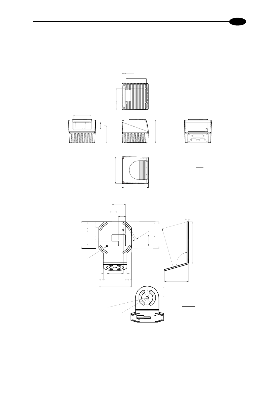
The following diagrams give the overall dimensions of the reader standard model, oscillating
mirror model and mounting brackets. They may be used for their installation. Refer to par.
2.4 for correct positioning of the scanner with respect to the code passage zone.
4.33
4.45
110
113
99 3.
90
76
30
74
2.99
1.
18
2.85
85
16.5
30
3.34
0.65
60 2.
36
1.18
mm
inch
Figure 8 - DS6400 Overall Dimensions
=
=
=
=
82 3.
22
20 0.
78
50
1.
96
18 0.
71
N
°2
25
0.
98
10
0.4
22
0.86
42
1.65
Ø4
.1
N°
2
Ø0
.16
N°
2
4.5
N°
4
SL
OT
S
0.1
8 N
°4
SL
OT
S
82 3.
22
50 1.
96
35 1.
37
50
1.96
72
2.83
100
3.93
4
0.15
13
0
5.
12
12
6
4.9
6
106°
73.2
2.88
36
1.
41
8.5 N
°2 SL
OTS
0.33 N
°2 SL
OTS
Ш8
.5
Ш0
.33
mm
inch
Figure 9 – ST-237 Mounting Bracket Overall Dimensions
9