Datalogic Scanning DS8100A User Manual
Ds8100a, General view
DS8100A QUICK GUIDE
DS8100A
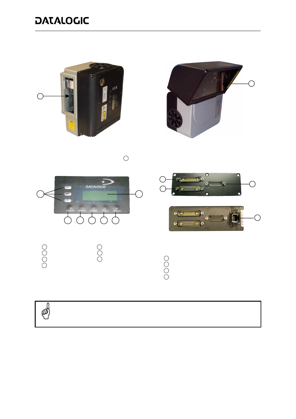
General View:
Linear Model
Oscillating Mirror Model
Figure A
Laser Beam Output Windows
1
Figure B
Programming Keypad
1
Phase On LED (Yellow)
3
Power On LED (Green)
2
TX Data LED (Green)
5
Network LED (Red)
6
Encoder LED (Yellow)
4
LCD Display
7
Standard
Ethernet
Figure C
Lonworks 17-pin Male Connector
1
Lonworks 17-pin Female Connector
2
Serial Interface and I/O 26-pin male Connector
3
Harting RJ Industrial® Modular female Connector
4
NOTE
For further details on product installation, see the complete Reference Manual available on the
configuration CD-ROM included with this product.
1
3
2
4
7
1
2
3
4
5
6
1
1