Herrmidifier Herrmidicool User Manual
Page 5
Herrmidicool IOS Manual
I n s t a l l a t i o n , O p e r a t i o n & S e r v i c e M a n u a l
5
www.herrmidifier-hvac.com
Supply Power
1. Supply power of 120 VAC, 5 amps is required.
2. Field wiring of the main power supply is connected
directly to the terminal strip in the control cabinet. A
ground lug is provided for the ground wire.
3. Install external overcurrent protection and provide wiring
in accordance with the NEC, state and local codes.
4. Power supply must be “clean;” free of spikes, surges
and sags; +10%, -15% of nominal. Ground should be
true earth ground.
Controls
Control Circuit Connections
The Herrmidicool has the capability to utilize one of three
types of control schemes:
1. On/Off
2. Proportional (DDC Interface)
3. Proportional + Integral
Controls may be supplied by the factory or others. The
following information applies to all controls factory supplied
or furnished by others. All external electrical control circuits
are to be connected to the unit using the terminal strip located
in the electrical compartment. Field wiring from humidistat/
BAS to humidifier and between safety devices, such as high
limit humidistat and air proving switches, should be 18 AWG
stranded or 20 AWG solid wire. If conduit is not used with
the controls wiring, install the black plastic fingered bushing
(in accessory pack) and completely seal with RTV Silicone.
Wall devices should be mounted at a height similar to that
of a typical thermostat and should be located in an area that
will provide good representation of the overall space being
humidified.
Do not mount wall devices directly in the air
stream of a supply grille.
Duct control devices should be mounted in a location where
the humidity and temperature are uniform, usually the return
duct.
Duct high limit devices should be mounted downstream
of the evaporative surface, far enough that under normal
conditions in the air stream, typically 10 ft. The device
should be located such that it can sense humidified air as
it approaches saturation. Do not mount in dead air spaces
such as inside of corners.
Air proving devices should be mounted so that they sense
airflow (or the absence of it). Wire the device so that it closes
when airflow is present and will open when there is no airflow.
The purpose of the device is to prove that airflow is present
before humidification is distributed into the duct.
Your application specific wiring diagram will detail exact field
wiring connection points for your unit.
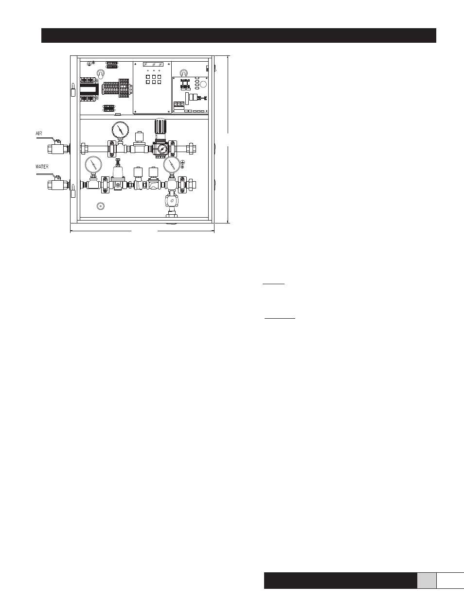
24”
28”
Cabinet Depth = 8.3”