Groth 3000 Series User Manual
Page 7
4
INSPECTION AND INSTALLATION
The regulator is packaged and supported to prevent
damage or contamination in shipping. It should be
similarly protected during subsequent handling and
storage. Always keep all ports plugged to prevent
intrusion of foreign materials. Before installation,
inspect the unit visually. If there are indications of
physical damage or internal contamination, the
regulator must be disassembled, cleaned and
inspected before installation. If factory set, the
spring adjustment cap and the orifice selector locking
screw must be secure. Report any shipping damage
to your carrier.
The regulator inlet and outlet connections are 1" NPT
(F) or 1" 150# RF ANSI flange. The regulator must
be installed level, the direction of the flow is marked
on the body. It is to be installed in accordance with
accepted piping practices. Full bore block valves
should be installed upstream and downstream of the
regulator and in the sense line to allow it to be
removed from the system for maintenance.
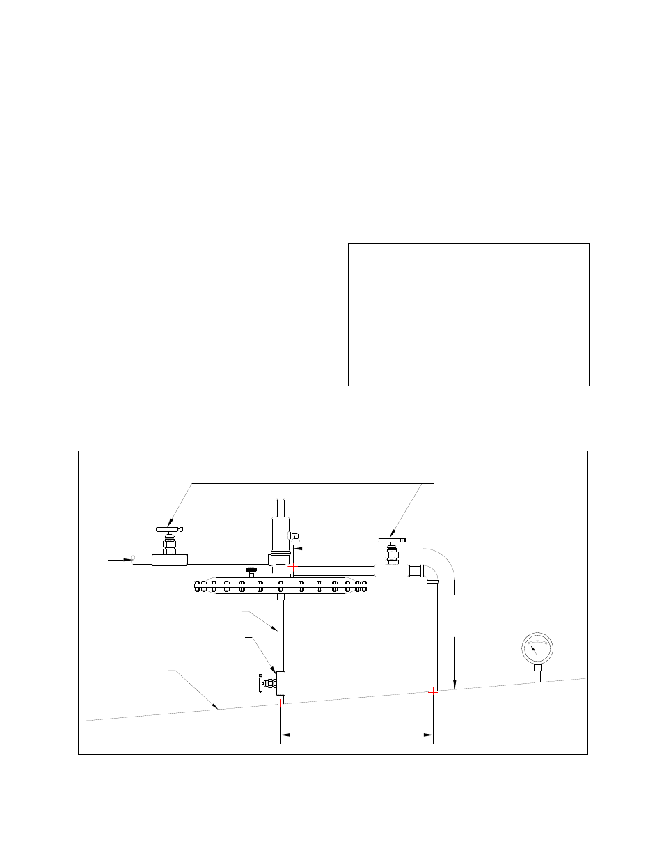
The regulator discharge line must be as short as
possible to obtain the rated gas flow rate. It is not
recommended to exceed a 5' length of 1" SCH 40
pipe. Consult with the factory for piping
recommendations if it is necessary to install the
regulator a greater distance from the tank. The
supply line must be capable of providing the rated
flow at the minimum supply pressure. The sense line
should be minimum 300" ID tubing and is to be
connected to the tank at least 12" from the regulator
discharge line (See. Figure 4).
WARNING
Regulator flow capacity listed in Table 2 is based on
tests with 5' of 1" SCH. 40 discharge pipe and a 2"
supply hose reduced to 1" pipe at regulator supply
port. Depending on discharge line size, length and
number of fittings, regulator flow capacity may be
less than published curves. Supply and discharge
piping should be designed to minimize losses at
desired flow condition. Consult factory for non-
standard installation regarding flow capacity.
Figure 4: Blanketing Regulator Installation
TANK
PRESSURE
GAUGE
BLANKET
GAS
SUPPLY
DISCHARGE
PIPING
5' MAX
LENGTH
12" MIN
BLOCK VALVE-1" MIN FULL BORE
(2)
(3)
(1)
SENSE LINE
BLOCK VALVE-1/2" MIN FULL BORE
TANK ROOF