Groth 3000 Series User Manual
Page 13
10
Remove the hex nuts, lockwashers, and hex bolts
(items 18, 17, & 16 respectively). Remove the upper
diaphragm case assembly [12] straight up.
Loosen the vise and remove the lower diaphragm
case with the pipe nipple still intact. Turn the upper
diaphragm case assembly upside down and use a vise
to hold on to the body [20].
Insert the 3/8" open end wrench through the inlet port
and hold on to the piston at the wrench flats while
loosening the countersunk screw [37] (See Figure
12).
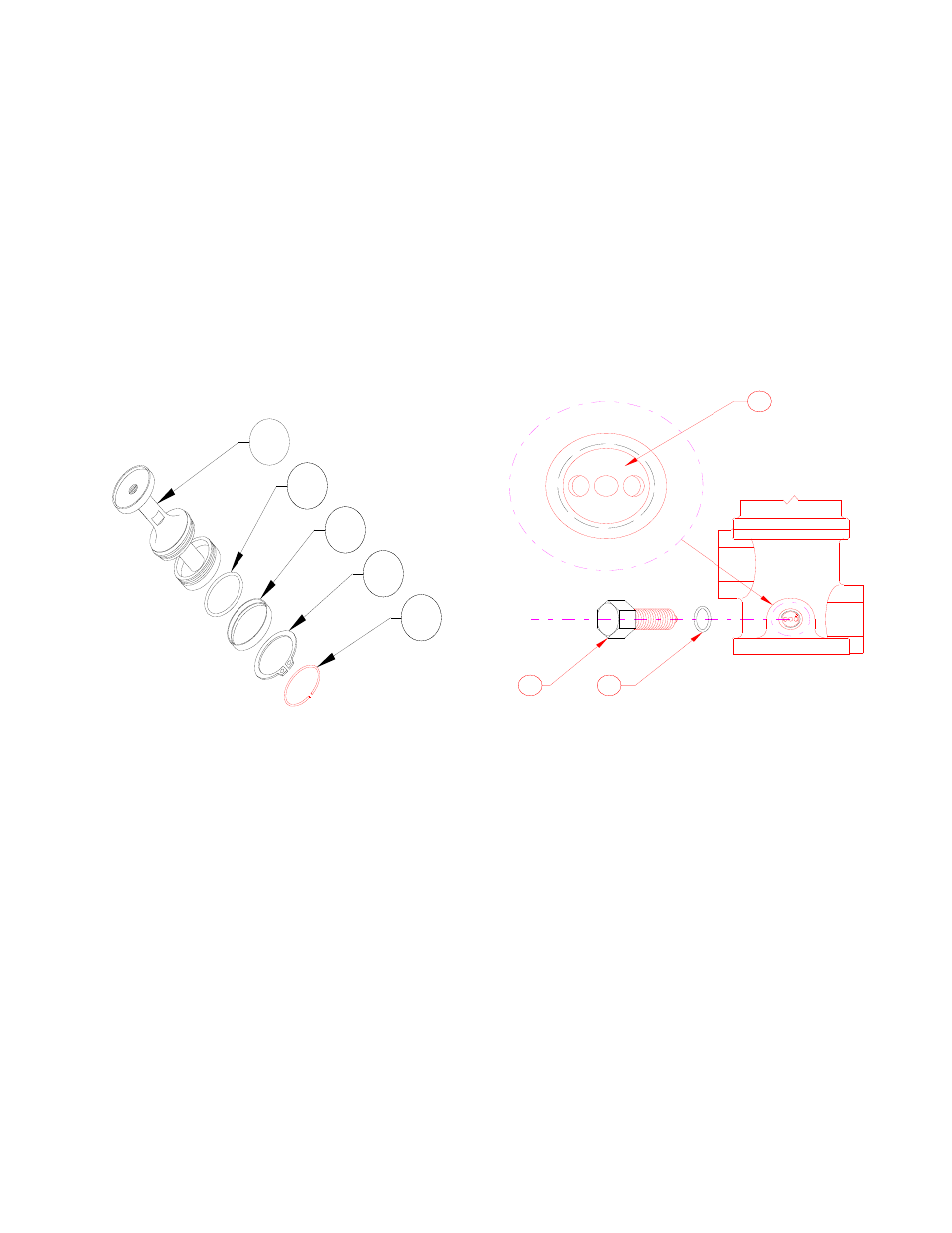
Figure 8: Piston Assembly - "Exploded"
24
25
31
32
33
Remove the washer [38], the diaphragm [14], the
diaphragm support plate [13] and then the back-up
plate [19].
Use a 3/16" Allen hex key and remove the
countersunk screws [30]. Remove the upper
diaphragm case [12].
Lift the piston sub-assembly [24] straight up and
remove from the body for disassembly. Lay the
piston subassembly horizontally on a clean flat
surface. Hold the piston at the wrench flats and
remove the lower pin [26], the diaphragm retainer
[9], the diaphragm [21], the O-Ring [22] and then the
guide ring [23].
Remove the piston sub-assembly from the body.
Remove the lift stop ring [33] from the groove by
expanding the ring slightly; and slide it over the
piston with care. Do not overexpand the ring.
Remove the retaining ring [32] with retaining ring
pliers. Expand retaining ring just enough to slide
over the piston. Be careful not to scratch the piston
surface. Remove the O-Ring retainer [31] and the o-
ring [25].
Figure 9: Orifice Sleeve Orientation
2
3
2
34
36
35
Refer to "FLOW CAPACITY SETTING" and
warnings before disassembling lockdown screw [36]
from body. Loosen and screw the lock down screw
[36] completely out of the Body. Before removing
the orifice selector sleeve [34], make note of its
position by looking through the 1/2" lock down
screw port. There will be a number stenciled on the
sleeve indicating the position of the sleeve. Note this
number for re-assembly. Refer to Tables 2 & 6 to
determine flow capacity of the regulator at a specific
open position.
All components should be examined for damage or
wear. Replace all seals and diaphragms. Prior to
reassembly, make sure all components are clean and
free of contamination.