Groth 3000 Series User Manual
Page 14
11
ASSEMBLY
Before assembly note the following material and tool
requirements:
1. Diaphragms, O-Rings, gasket, vents and
spring as listed in Table 7:
Recommended Spare Parts on page 8.
2. Lubricants & Thread Sealants
A.
Silicone
Grease
Dow Corning No. 33
B.
Anti-Galling
Lubricant
Dow Corning G-N Metal
Assembly
Spray
C.
Thread
Sealant
Loctite Threadlocker No. 222
D.
Fluoropolymer
tape
3.
Assembly
Tools
A. 7/16" - 1" box end wrenches
B. 3/8" open end wrench*
C. 3/16" Allen key
* Wrench must be 16" long for flanged units.
All screw threads and static O-Ring should be lightly
greased with silicone grease. Lubricate the piston
OD at both ends and the spring adjusting screw with
an anti-galling spray. If the greases listed above are
not compatible with the tank vapors, use equivalent
lubricants for that media. All pipe threads are to be
wrapped with Fluoropolymer tape or suitable pipe
thread sealant applied sparingly.
Before installing the orifice selector sleeve, read the
section entitled "FLOW CAPACITY SETTING" and
related warnings on page 7. Install the orifice
selector sleeve [34] into the regulator body. Observe
the sleeve position locking hole by looking in the
locking screw hole in the body. The hole in the
sleeve should be exactly centered in the screw hole.
If the holes do not line up exactly, invert the sleeve
and reinstall. The position indicating numbers will
also be seen through the screw hole.
These numbers indicate % open and flow capacity
according to Tables 2 and 6. Make sure that the
sleeve position is on the same number as when
disassembled, or on the number that provides the
specified flow requirements.
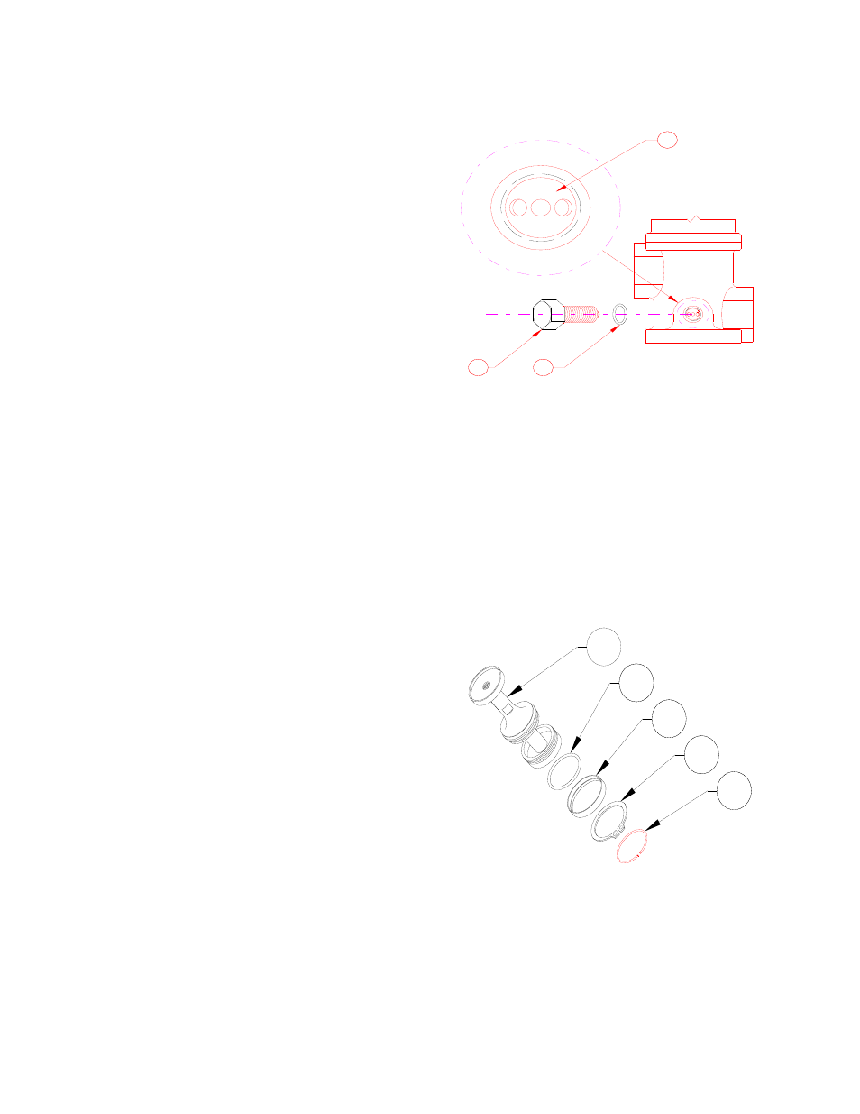
Figure 10: Orifice Sleeve Orientation
2
3
2
34
36
35
Grease the locking screw O-ring [35] and slip it over
the screw threads. Thread the locking screw [36]
into the body, finger tight, until the point enters the
sleeve and the head seats onto the O-ring. Then
wrench tighten the head firmly against the body,
compressing the O-ring.
Note: Damage to the sleeve will occur if force is
applied with the point of the locking screw.
Figure 11: Piston Assembly - "Exploded"
24
25
31
32
33
Assemble the piston sub-assembly according to
Figure 11. Install the O-Ring [25] from the top end
of the piston. Do not rotate the o-ring, but stretch it
just enough to clear the piston diameter. When
installing the retaining ring [31], snap ring [32] and
lift stop ring [33] expand the rings just enough to