Grip Factory Munich GF-16 User Manual
Page 9
GF-16 Crane System Instruction Manual
Page: 8
Version 2
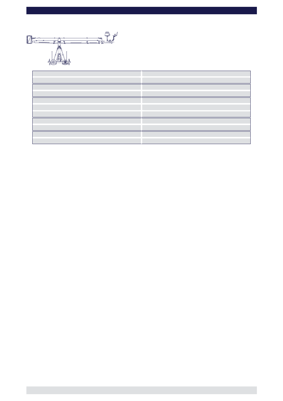
Front extension arms required
1 x 200 cm / 6' 6” + 1 x 100 cm / 3’ 3”
Rear extension arm required
1 x 192 cm / 6' 3”
Lift range
575 cm / 18’ 10”
Maximum Euro-adapter height
501 cm / 16' 5 "
Lift capacity (working load) 2 pers. + accessories
250 kg / 550 lbs
Counterweight required for max. load
424 kg / 932 lbs
Counterweight required to balance empty arm
36 kg / 79 lbs
Crane weight (excluding dolly and weights)
678 kg / 1495 lbs
Dolly weight (unit weights see page 46)
244 kg / 536 lbs
Arm reach (pivot to camera head mount)
434 cm / 14’ 2”
Length of rear end (pivot to outside of bucket)
278 cm / 9’ 1”
Continue from § 12, page 6
13. Connect the 100cm / 3’ 3” extension to extension number 1. Slip the connection
flanges into each other and secure with the provided safety pin.
Note: The 100cm / 3’ 3” section must be supported by a suitable support stand or
rostrum.
Tip:
To avoid the sections jamming or getting stuck make sure that the sections
are joined parallel. Using a small amount of lubricant also helps. We suggest
rubbing the joints with an oiled rag prior to assembly.
14. Connect a 200cm / 6’ 6” parallelogram rod to the parallelogram connection on the
middle section and secure it with the provided safety pin.
15. Connect the 100cm / 3’ 3” parallelogram rod to the first parallelogram connection and
secure it with the provided safety pin.
16. Connect the angle adjuster to the end of the 100cm / 3’ 3” extension. Release the
angle adjuster by removing the safety pins from the side of the angle adjuster. Secure
the angle adjuster to the 100cm / 3’ 3” extension with a removed safety pin.
Tip:
The angle adjuster has two sidewise safety pins. These are either used for
the angle adjusters transport position or to secure the connections between
angle adjuster and extension as well as angle adjuster and platform.
17. Connect the 100cm / 3’ 3” parallelogram rod to the rod on the angle adjuster and
secure it with the provided safety pin.
Tip:
The angle adjuster has an integrated leveller. By turning it, the vertical plate
on the angle adjuster can be set to a perfect right angle. Correct setting of
the angle adjuster enhances the crane’s balance.
18. Connect the platform to the angle adjuster and secure with the removed safety pin
from the side of the angle adjuster. Ensure that the platform is level.
19. Remove the support stand or rostrum supporting the counterweight bucket section.
20. Then unlock the tilt friction.
Before operation, all locking pins, locking screws etc should be inspected to ensure
that all assembly sections are securely fastened.
Read “Balancing the crane arm” on page 44.