Rigging system, General, Rigging harness assembly – Grip Factory Munich GF-16 User Manual
Page 10
GF-16 Crane System Instruction Manual
Page: 9
Rigging system
The rigging system must be used from Version 3 upwards.
General:
For versions using more than 3 x 200cm long sections (versions 7 to 15), a double
rigging system must be mounted. During assembly, to support the arm and ensure that it
does not dip, mount the lower rigging system as soon as crane arm sections 2, 3 or 4
(depending on version) are mounted. When the lower rigging is mounted and adjusted,
only then add on section 4, 5 and 6 etc. As soon as the last section is mounted, then
assemble the top rigging system.
Tip: Do not load weights until the rigging system is mounted.
Never use the crane with 2 or more than 2 x 200cm sections mounted without rigging.
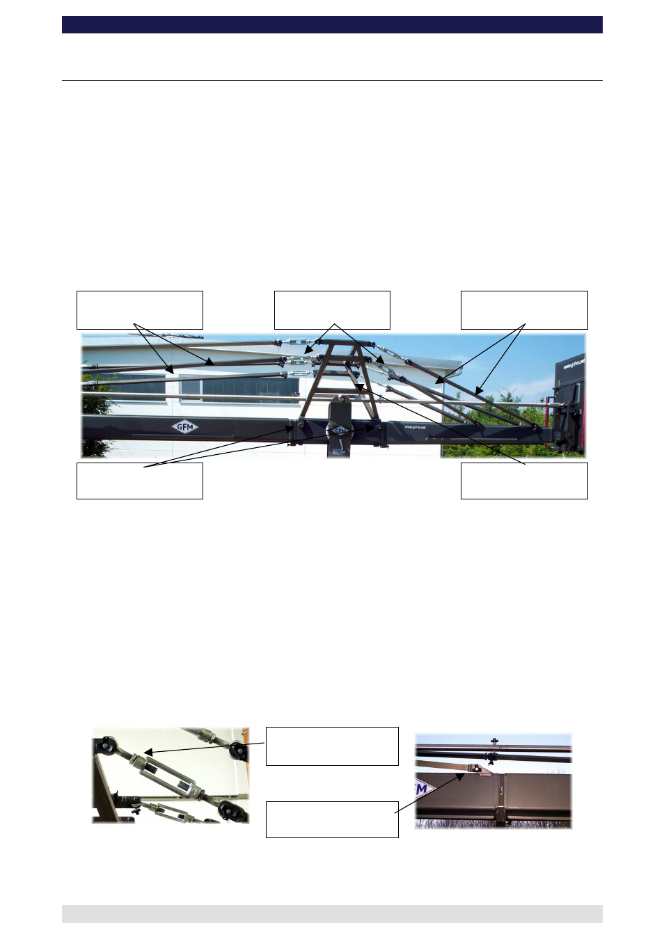
Standard Rigging rods
Turnbuckles
Rear Rigging rods
Locking bolts
Rigging harness
Rigging Harness Assembly:
1.
Connect the rigging harness to both sides of the middle section and connect with the
2 cross bars. Then ensure that the 4 locking bolts are inserted and tightened fully to
the Pivot Section. Ensure that the 4 locking pins securing the 2 cross bars are
inserted fully.
2.
Connect the turnbuckles to the rear rigging harness and in turn connect the 4 rear
rigging rods to the 4 rigging connections on the counterweight bucket arm. Connect
the 2 x 90cm rods to the lower turnbuckles and in turn to the inner connections on the
rear section. Then connect the 2 x 150cm rods to the top turnbuckles and in turn to
the outer connections on the rear section. Ensure that the locking pins are inserted
fully. Hand tighten the rods by turning the turnbuckles until the 4 rods are taut, then
secure the turnbuckles with the locking nut.
Locking nut
Rigging connector
Note:
All rigging support brackets are identical, all rigging rod connectors are
identical, all standard rigging rods are identical.