Parallelogram supports – Grip Factory Munich GF-16 User Manual
Page 11
GF-16 Crane System Instruction Manual
Page: 10
In general, the length of the rigging system depends on the number of extension arms
assembled. For each extension arm, 1 rigging rod length consisting of 2 rods, is required.
From Version 7 upwards, i.e. more than 3 extensions a double rigging system is required
i.e. top and bottom.
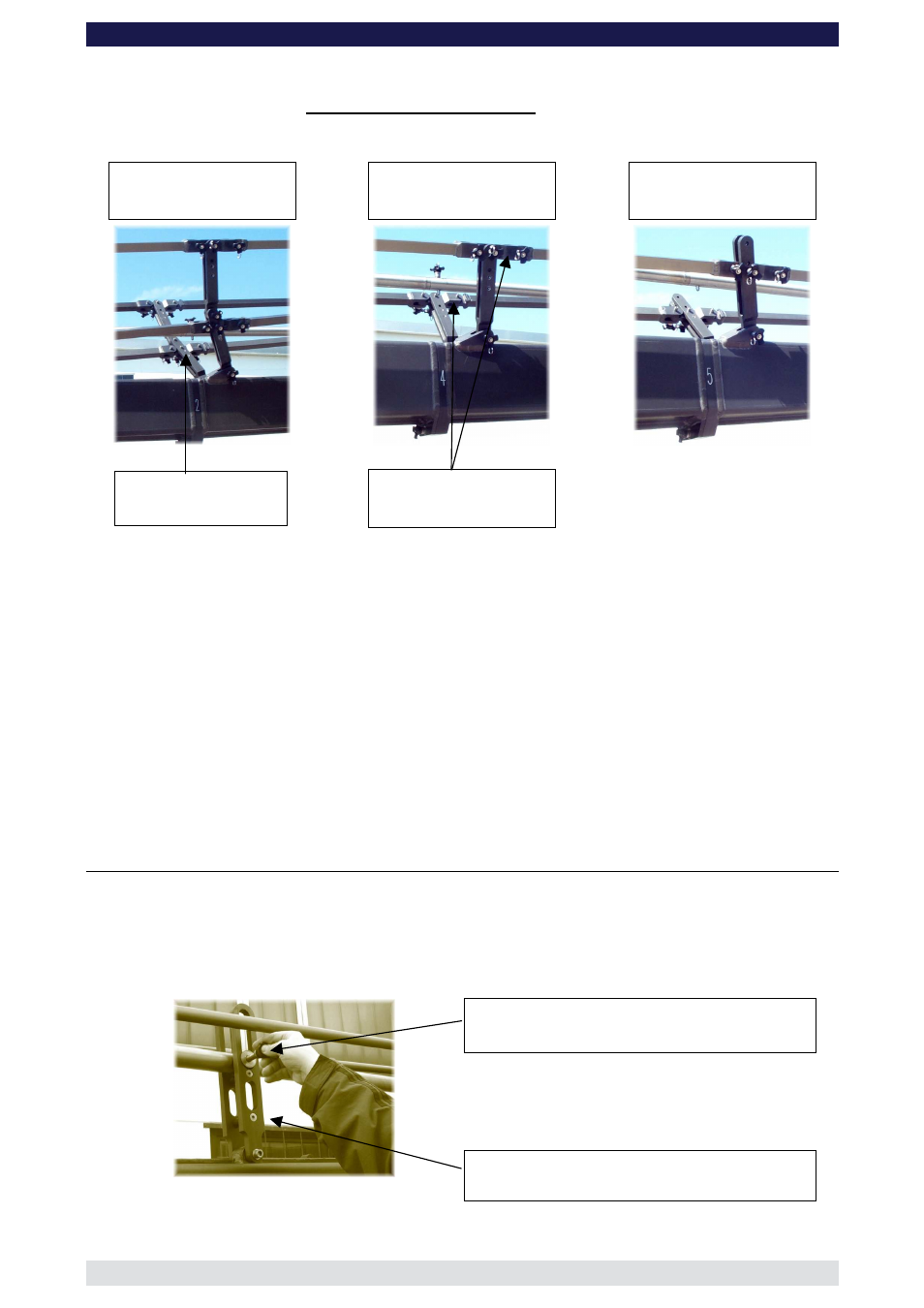
Top and lower rigging
support brackets, section
2
Rigging support bracket,
section 4
Rigging support bracket,
section 5
Rigging support
bracket
Rigging rod connector
The top rigging system is assembled in the same manner as the lower but starts off at the
top connection on the harness and finishes at the last extension.
The rigging system should be supported in certain positions with the Rigging Support
Brackets which connect to various sections. The Rigging Support Brackets are connected
to the Rigging Rod Connectors. Please refer to the individual versions as described on
pages 7 to 43.
It is important that the rigging system when taut, should run in a straight line and the crane
extensions should not bend or dip.
The second, fourth and fifth rigging rods are connected to the following rods via a
rigging rod connector.
Parallelogram Supports
By adding extension sections in numerical order plus the respective parallelogram rods, 15
standard versions can be built. When sections number 2, 4 and 6 as well as the Remote
section are used, support the respective parallelogram rods with the integrated
parallelogram supports.
Safety pin
Parallelogram support assembly
Parallelogram support