Line lo a d, Line load, Wiring – Greenheck Vari-Flow Air Management Systems (472966) User Manual
Page 5
5
Vari-Flow Air Management System
®
NOTE
All field installation and wiring of electrical
equipment must be done to meet NEC and local
codes.
Control Box
1. Run power to the control box from two
dedicated 120/1 20A breakers to the designated
terminals in the control box (one for lights, one
for controls).
2. If the variable frequency drives(s) are shipped
loose from the control cabinet, please refer
to the VFD wiring section for connection
instructions to the control box.
3. For hood systems connected to a fire system,
the fire system microswitch can be wired into
the designated terminals of the control box for
integration of fire system controls. The factory
default is exhaust on, supply off in fire mode. For
help with changing this parameter, please refer
to the controller setup portion of this manual.
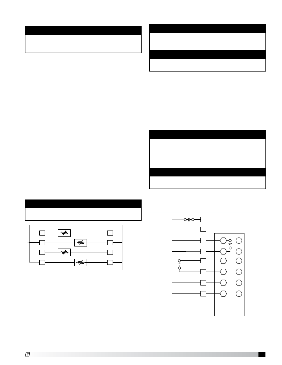
Resistive Temperature Detectors (RTD)
1. Wire the two leads of the sensors to designated
terminals in the control panel as shown below.
For more than four sensors, see wiring diagram
on page 7 or the one inside of control box door.
The two wires of the sensor are not polarity
sensitive. If more than one hood is being
controlled, be sure that the appropriate sensor is
wired in association with the appropriate hood.
Wiring
Variable Frequency Drives (VFD)
NOTE
If the VFD(s) are factory supplied and mounted in a
cabinet, all interface wiring is factory supplied and
this first step can be disregarded.
NOTE
If electrically commutated motors are being used,
VFDs will not be needed.
1. If the variable frequency drives are remotely
mounted, a six conductor 18 ga. Class 2 cable
must run between each VFD and the control
panel.
2. Bring power to the input of each VFD from a
dedicated power source using conduit. Each
power source shall be of the same voltage as
the respective fan and of a high enough amp
rating to handle the full load amp draw of the
respective fan.
3. To avoid interference between the conductors,
use separate conduit to wire from the VFD
output to the input power for the fan.
U1
93 - 24V (H)
42 - DO1
51 - DO4
45 - DO2
22 - DI COM
23 - DI2
25 - DI3
24V (C) - 92
DO1 COM - 41
DO4 COM - 53
24VAC
120VAC
R1
Hood Run
A1
A2
RED
Fault Indicator
GRN
Full Speed Indicator
21 - DI1
Full Speed
Fan On/Off
R3
14
11
Hood Lamp(s)
AR
Hood Light Contactor
N
H
TR1
L4
L3
PB3
PB2
Hood Lights Switch
PB1
AR
2
3
6
Hood Lights Relay
R1
Hood Run Contact
14
11
GRN
Hood Run Indicator
L1
7
4
6
15
14
9
13
11
H1
N1
Canopy Lighting circuit must not exceed 15A total current
AVPS - 13
31 - DI7
Fan Override
33
32
NO
C
44
45
46
47
48
49
PS1
PRESSURE
1
2
3
R5
Hood Light LED
Relay
A1
A2
R5
Hood Light LED Contact
14
11
GRN
Hood Light Indicator
L2
2
HL
DO2 COM - 44
12 - AI5
1 - AICOM
V1
VC
GGH 20/VAV Fan Mode
0 VDC - Fan Auto
5 VDC - Fan OFF
10 VDC - Fan On for Dry
+ VDC
COM
Interlock Connection
G
BK 14GA
16GA RD
16GA RD
PR
BK
BL
BL
BL
BL
YW
OR
OR
BL
YW
PR
OR
BR
BL
YW
OR
+
-
0
NEUTRAL
BR
OR
RD
DI5 - 28
DI COM - 22
AO4 - 78
AO COM - 71
AI6 - 15
BL
R2
Hood Run
A1
A2
BL
R3
MUA Run
A1
A2
48 - DO3
YW
1 - AICOM
2 - AI1
5 - AI2
T1
T2
17
16
19
18
1
21
20
7 - AI3
T3
BR
OR
OR
OR
10 - AI4
T4
23
22
OR
LL+
LL-
COM
R1
24
21
AICOM - 1
AO1 - 72
AO COM -71
AO2 - 74
AO3 - 76
DI COM - 22
DI4 - 26
24V (C) - 92
R4
14
11
R4
Shunt Trip Contact
Open on Shunt Trip
24
21
36
37
}
Fire Contact
24 VAC
24 VAC
24 VAC
120 VAC
24 VAC
EARTH - 91
40
41
42
43
Fire System
35
34
REMOVE
JUMPER
IF USED
R4
Fire & Shunt
Trip Relay
A1
A2
24 VAC
38
39
}
PR
PR
50
51
Tempering Status
Contact
Closed Tempering On
Open Tempering Off
BL
YW
YW
YW
BR
YW
OR
OR
OR
OR
OR
PR
PR
PR
PR
PR
BL
30 - DI6
29 - DI COM
PR
PR
PR
PR
RD
OR
BR
GN
RD
RD
34
31
56
57
52
53
54
55
OR
RD
RD
R1
RD
RD
OR
MC
MB
SC
S1
AC
A1
VFD
MUA1
L1
L2
L3
T1
T2
T3
}
}
LINE
LOAD
MC
MB
SC
S1
AC
A1
VFD
L1
L2
L3
T1
T2
T3
}
}
LINE
LOAD
EF1
AC
A1
MC
MB
SC
S1
L1
L2
L3
T1
T2
T3
}
}
LINE
LOAD
VFD
EF2
MC
MB
SC
S1
L1
L2
L3
T1
T2
T3
}
}
LINE
LOAD
AC
A1
VFD
EF3
R2
14
11
62
63
58
59
60
61
RD
RD
U1
24VAC
120VAC
R1
Hood Run
A1
A2
RED
Fault Indicator
GRN
Full Speed Indicator
Full Speed
Fan On/Off
R3
14
11
AR
Hood Light Contactor
N
H
TR1
L4
L3
PB3
PB2
Hood Lights Switch
PB1
AR
2
3
6
Hood Lights Relay
R1
Hood Run Contact
14
11
GRN
Hood Run Indicator
L1
7
4
6
15
14
9
13
11
H1
Canopy lighting circuit must not exceed 15A total current
Fan Override
33
32
NO
C
38
39
40
41
PS1
PRESSURE
1
2
3
R5
Hood Light LED Contact
14
11
GRN
Hood Light Indicator
L2
2
V1
VC
GGH20/VAV Fan Mode
0VDC - Fan Auto
5VDC - Fan OFF
10VDC - Fan On for Dry
+ VDC
COM
Interlock Connection
G
BK 14GA
PR
BK
BL
BL
BL
BL
YW
OR
OR
BL
YW
PR
OR
BR
BL
YW
OR
+
-
o
NEUTRAL
BR
OR
RD
BL
R2
Hood Run
A1
A2
BL
R3
MUA Run
A1
A2
YW
T1
T2
17
16
19
18
1
21
20
T3
BR
OR
OR
OR
T4
23
22
OR
R1
24
21
R4
14
11
R4
Shunt Trip Contact
Closes on Shunt Trip
22
21
36
37
Fire Contact
24 VAC
24 VAC
24 VAC
24 VAC
48
49
50
51
Fire System
35
34
REMOVE JUMPER IF USED
R4
Fire & Shunt Trip Relay
A1
A2
24 VAC
44
45
PR
PR
47
46
Tempering Status Contact
Closed Tempering On
Open Tempering Off
BL
YW
YW
YW
BR
YW
OR
OR
OR
OR
OR
PR
PR
PR
PR
PR
BL
PR
PR
PR
PR
RD
OR
BR
GN
RD
RD
34
31
58
59
54
55
56
57
OR
RD
RD
R1
RD
RD
OR
REMOVE JUMPER
IF USED
93-24V (H)
42-DO1
51-DO4
45-DO2
12-AI5
1-AICOM
48-DO3
1-AICOM
2-AI1
5-AI2
7-AI3
10-AI4
30-DI6
29-DI COM
80-AOV HOT
35-DIV HOT
DI COM-22
DI2-23
DI3-25
24V (C)-92
DO1 COM-41
DO4 COM-53
DI1-21
AVPS-13
DI7-31
DO2 COM-44
DI5-28
DI COM-22
AO4-78
AO COM-71
AI6-15
AICOM-1
AO1-72
AO COM-71
AO2-74
AO3-76
DI COM-22
DI4-26
EARTH-91
AOV COM-79
DIV COM-34
DO3 COM-47
BL
BL
BL
YW
YW
YW
Hood Lamp(s)
N1
R5
Hood Light LED Relay
A1
A2
HL
16GA RD
16GA RD
120 VAC
52
53
MC
MB
SC
S1
AC
A1
VFD
MUA1
L1
L2
L3
T1
T2
T3
LINE
LO
A
D
24V (C)-92
24V (H)-93
R3
24
21
42
43
BL
YW
}
24 VAC FAN ENABLE
TO MUA
MC
MB
SC
S1
AC
A1
VFD
L1
L2
L3
T1
T2
T3
LINE
LO
A
D
EF1
AC
A1
MC
MB
SC
S1
L1
L2
L3
T1
T2
T3
LINE
LO
A
D
VFD
EF2
MC
MB
SC
S1
L1
L2
L3
T1
T2
T3
LINE
LO
A
D
AC
A1
VFD
EF3
R2
14
11
64
65
60
61
62
63
RD
RD
}
}
}
}
}
}
}
}
}
}
}
9/3/2010
Turned off several layers; Borders/Legend.
Adjusted the text so it would be readable.
Was overlapping on lines.
Changed line weight.
Changed to Black/CMYK.
Converted from a .dwg drawing.
NOTE
The RTD’s should not be exposed to direct flame.
The RTD’s are rated up to 250°F
NOTE
The VFD input voltage parameter (E1-01) and motor
overload parameter (E2-01) need to be set to the
motor nameplate FLA. Refer to the Quick Start
Guide from Yaskawa (pages 83-100) for setting these
parameters on the Yaskawa drive.
NOTE
Be sure to use appropriately sized wire for the full
load amp draw.