Greenheck Vari-Flow Air Management Systems (472966) User Manual
Page 10
10
Vari-Flow Air Management System
®
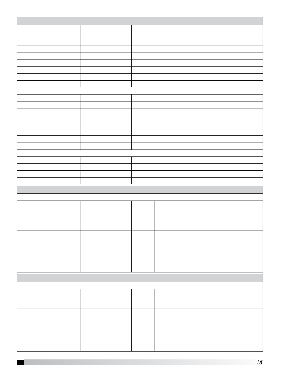
Temperature Sensors -
continued
Temp Sensor on EF4*
Descriptors/Value Default
Use
T1 to EF4
No / Yes
No
Indicates if T1 is linked to EF4
T2 to EF4
No / Yes
No
Indicates if T2 is linked to EF4
T3 to EF4
No / Yes
No
Indicates if T3 is linked to EF4
T4 to EF4
No / Yes
No
Indicates if T4 is linked to EF4
T5 to EF4
No / Yes
No
Indicates if T5 is linked to EF4
T6 to EF4
No / Yes
No
Indicates if T6 is linked to EF4
T7 to EF4
No / Yes
No
Indicates if T7 is linked to EF4
T8 to EF4
No / Yes
No
Indicates if T8 is linked to EF4
Temperature Sensor on EF5*
T1 to EF5
No / Yes
No
Indicates if T1 is linked to EF5
T2 to EF5
No / Yes
No
Indicates if T2 is linked to EF5
T3 to EF5
No / Yes
No
Indicates if T3 is linked to EF5
T4 to EF5
No / Yes
No
Indicates if T4 is linked to EF5
T5 to EF5
No / Yes
No
Indicates if T5 is linked to EF5
T6 to EF5
No / Yes
No
Indicates if T6 is linked to EF5
T7 to EF5
No / Yes
No
Indicates if T7 is linked to EF5
T8 to EF5
No / Yes
No
Indicates if T8 is linked to EF5
Temperature Sensors Connected
T1
No / Yes
Yes
Indicates if T1 is connected
T2
No / Yes
No
Indicates if T2 is connected
T3
No / Yes
No
Indicates if T3 is connected
T4
No / Yes
No
Indicates if T4 is connected
Temperature Interlock (IMC Compliance)
Temp Interlock*
TempInt Enabled
No/Yes
Yes
If set to yes, Temperature Interlock feature
is enabled. Exhaust fan will start if hood
temperature exceeds the Temperature Interlock
set point and will run until the hood temperature
falls below set point for the off delay time.
Set Point
°F
90°F
If the temperature of the hood exceeds this set
point, the exhaust fan will start automatically
regardless of the operating mode of the fan
selected by the operator.
Off Delay Time
Minutes
10 min
The amount of time the fans remain on after
the temperature in the hood goes below the
temperature set point.
Make-Up Air
Make-Up Air Set Points*
MUA Mode
Pres / Trak
Pres
Indicates the operating mode of the MUA
Pressure
Inches of WC x 100
-
Differential air pressure measured from the
control space to the outside or adjacent room.
Set Point
Inches of WC x 100
5
The desired space pressure set point.
(adjustable from -.30” WC to + .30” WC)
MUA Speed
0-100%
-
The actual output speed for the MUA
Max Speed Set*
0-100%
100%
The maximum output control limit for the MUA
VFD or damper set. Must be set to a value
that ensures proper design full flow CFM.
(Adjustable from 0% to 100%)
* To see values, you need to log in.