Installation - electrical wiring, Step 5 wire the accessories, Step 6 wire the optional evaporative cooler – Greenheck DG / DGX with Pilot Ignition (463555 IOM) (Pre-2008) User Manual
Page 9: Step 7 check recirculation / vav operation, Tscp has number-to-number wiring
Step 5 Wire the Accessories
Reference the ladder diagram on the inside of the
control center door for correct wiring of the following
accessories:
Step 6 Wire the Optional Evaporative
Cooler
Reference the ladder diagram on the inside of the
control center door for correct wiring of the pump and
the optional water valves.
Step 7 Check Recirculation / VAV
Operation
Two Position Damper Control
Turn the recirculating switch on the remote control
panel to each position and confirm that the return air
damper adjusts accordingly. The damper actuator
may take a few minutes to open or close.
Two Speed
Turn the fan speed switch on the remote control
panel to each positions and confirm that the fan
speed adjusts accordingly
Potentiometer Control
To test potentiometer operation, turn the
potentiometer to the two extremes. With 80/20
recirculation, confirm that the return air damper fully
opens and fully closes. The damper actuator may
take a few minutes to open or close. With variable
volume, make sure the fan goes to maximum and
minimum speed.
Building Pressure Control
See Installation - Building Pressure Control for
building pressure set-up and operation check.
External Signal Control
See Operation-VAV and Recirculating Units for
additional information. External 2-10 VDC / 4-20 mA
signal required.
NOTE!
Large evaporative coolers may require a
separate power supply.
NOTE!
TSCP has number-to-number wiring.
NOTE!
Wiring to the Selectra Stat, should be in
separate conduit or run with shielded cable.
Installation - Electrical Wiring
Installation
NOTE!
For maintenance issues associated with variable
frequency drives, consult the drive’s manual
supplied with the unit. The drives are
programmed at the factory and should not need
any adjustment during installation and start-up.
For kitchen applications, the drive may be
located in the kitchen or in the unit.
NOTE!
Blower Start-Up, steps 1-4 should be
performed before the blower is run.
• Selectra Stat
• Room Override
• Blower Switch
• Heat Switch
• Indicating Lights
• Dirty Filter Indicator
• TSCP
• KSCP
9
70
65
75
80
85
90
60
55
(OPTIONAL)
BLOWER
DIRTY FILTERS
MAIN VALVES
EXHAUST
SUPPLY
HEAT
(OPTIONAL)
GREENHECK
®
PHOTOHELIC
70
65
75
80
85
90
60
55
(OPTIONAL)
BLOWER
DIRTY FILTERS
MAIN VALVES
EXHAUST
SUPPLY
HEAT
(OPTIONAL)
GREENHECK
®
70
65
75
80
85
90
60
55
GREENHECK
®
(OPTIONAL)
BLOWER
DIRTY FILTERS
MAIN VALVES
RECIRCULATION
EXHAUST
SUPPLY
HEAT
(OPTIONAL)
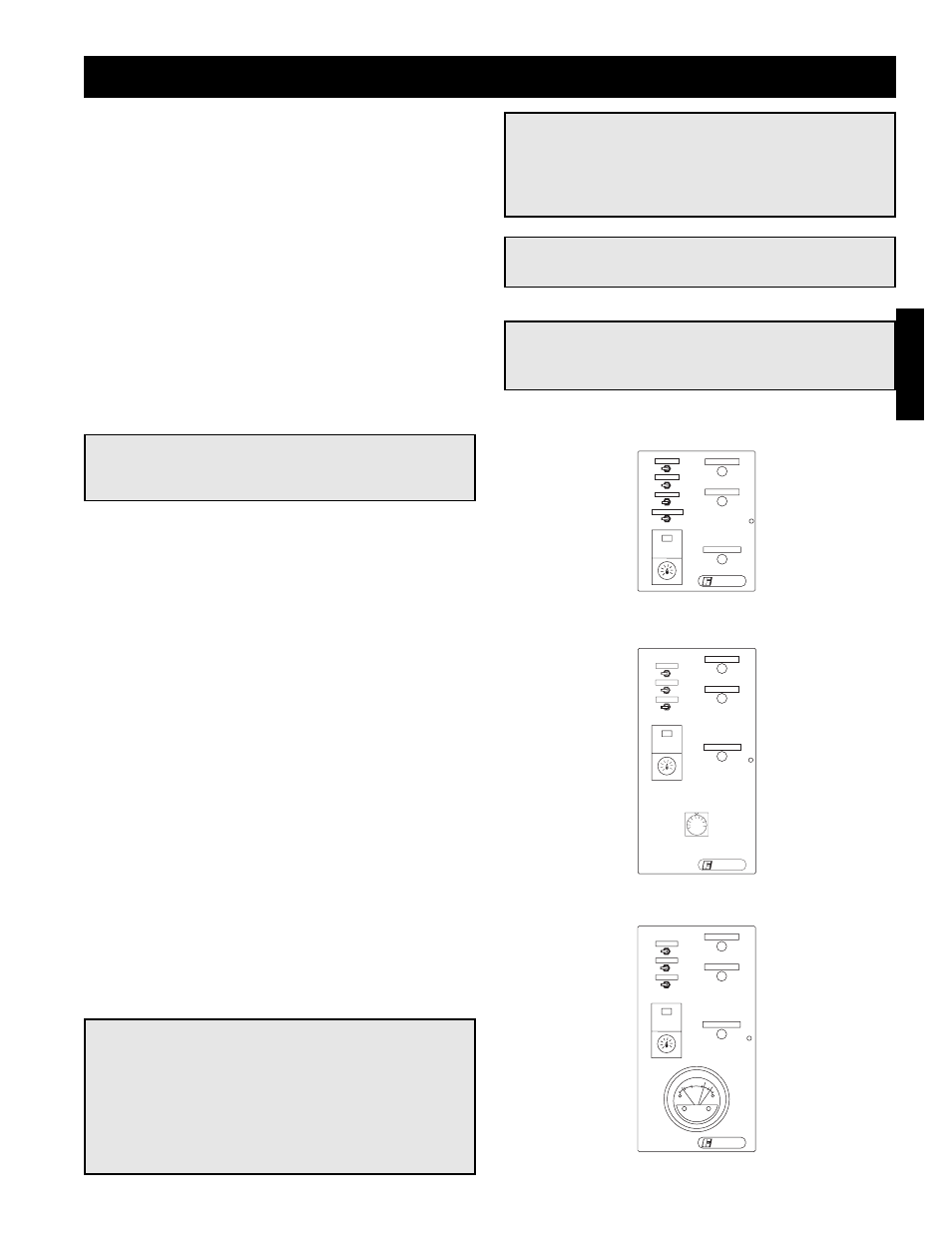
2-Position Damper Control
Building Pressure Control
Potentiometer Control