Overall wiring plan view for switch panels, Circuit diagrams, Shipped loose hood mounted – Greenheck Canopy Hoods (452413 IOM) User Manual
Page 28: Kitchen hoods • type i and type ii 28
Kitchen Hoods • Type I and Type II
28
®
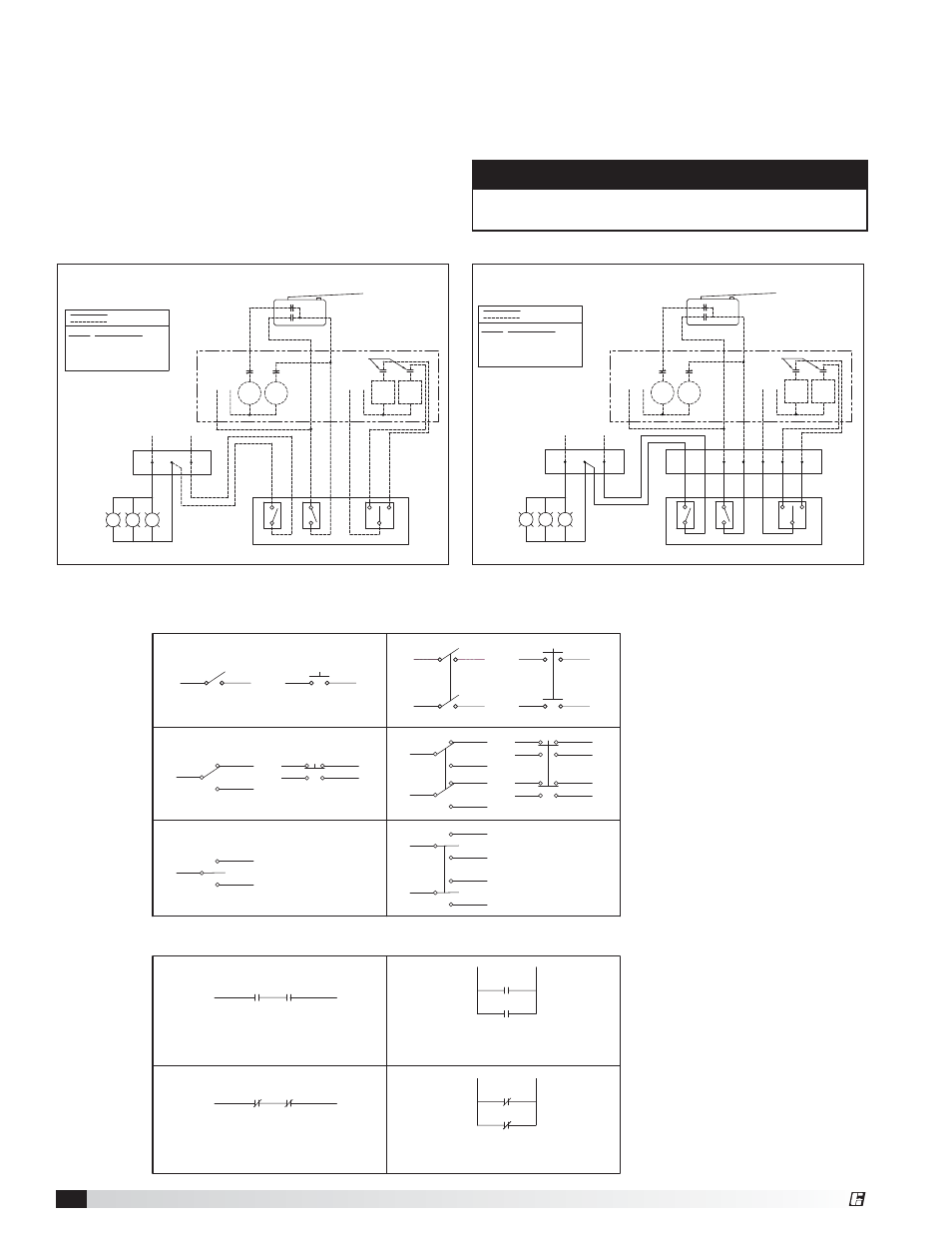
Overall Wiring Plan View for Switch Panels
The diagrams below show typical wiring for combined
exhaust and supply switching when the switches are
shipped loose for remote mounting, and for hood
mounted switches.
The diagram shows how to wire the exhaust and
supply fan starters to the switches and fire suppression
contact. Typically, supply fans will be turned off and
exhaust fans will be turned on (or continue to run) in the
event the fire system is activated. The fire suppression
micro-switch is provided as part of the fire suppression
system and is normally mounted in the fire system
control box.
EXH
STR
FAN
CONTROL
VOLTAGE
H
N
SUP
STR
FAN
OL
FANS
LIGHTS
SWITCHES
HOOD LIGHTS
VOLTAGE FOR LIGHTS
J-BOX ON
TOP OF
HOOD
SUP
HTR
CTRL
SUP
CTRL
COOL
HEAT/COOL
CONTROL
VOLTAGE
SUPPLY FAN
CONTACT
BLACK
WHITE
N
H
H
N
NC
NO
COM
OL
FIRE SUPPRESSION
MICRO-SWITCH/CONTACTS
120 VAC
TYPICAL WIRING FOR COMBINED
EXHAUST & SUPPLY SWITCHING (SHIPPED LOOSE)
FIELD WIRING
FACTORY WIRING
COM
NO
NC
STR
Normally-open
Normally-closed
LABEL DESCRIPTION
Common
Motor Starter
OL
Overload
FAN STARTERS PROVIDED
BY OTHERS
EXH
STR
FAN
CONTROL
VOLTAGE
H
N
SUP
STR
FAN
OL
FANS
LIGHTS
SWITCHES
HOOD LIGHTS
VOLTAGE FOR LIGHTS
FAN STARTERS PROVIDED
BY OTHERS
J-BOX ON
TOP OF
HOOD
SUP
HTR
CTRL
SUP
CTRL
COOL
HEAT/COOL
CONTROL
VOLTAGE
SUPPLY FAN
CONTACT
BLACK
WHITE
N
H
H
N
FIELD WIRING
FACTORY WIRING
NC
NO
COM
OL
FIRE SUPPRESSION
MICRO-SWITCH/CONTACTS
120 VAC
COM
NO
NC
STR
Normally-open
Normally-closed
LABEL DESCRIPTION
Common
Motor Starter
OL
Overload
BLACK
BLACK
BROWN
RED
J-BOX ON
TOP OF
HOOD
ORANGE
PURPLE
YELLOW
TYPICAL WIRING FOR COMBINED
EXHAUST & SUPPLY SWITCHING (HOOD MOUNTED)
Shipped Loose
Hood Mounted
Circuit Diagrams
ON
ON (NO)
ON
ON (NO)
ON
ON
ON (NO)
ON
ON (NO)
ON
ON
ON (NO)
ON (NO)
ON
ON
ON
ON (NC)
ON (NC)
ON
ON (NC)
ON (NC)
ON
ON (NC)
ON (NC)
OFF
OFF
OFF
OFF
OFF
OFF
OFF
OFF
OFF
On if both are not activated
Off if both are activated
Off if either are not activated
Off if both are not activated
On if both are activated
Off if either are not activated
Off if both are activated
On if either is activated
On if either is activated
On if both are activated
Off if both are not activated
Off if either not activated
Single Throw
Single Pole
Double Pole
Double Throw
Double Throw
Center Off
Series Circuit
Normally
Open
Contacts
Parallel Circuit
Normally
Closed
Contacts
NOTE
Wiring examples for use when a control panel is not
provided as part of the kitchen package.