Kitchen hoods • type i and type ii 27 – Greenheck Canopy Hoods (452413 IOM) User Manual
Page 27
Kitchen Hoods • Type I and Type II
27
®
DISCONNECT
SWITCH IN
CONTROL
CENTER
OPTIONAL
DISCONNECT
(FIELD OR
FACTORY
INSTALLED)
TYPICAL
EXHAUST
FAN
TYPICAL MUA FAN
WITH CONTROL CENTER
TYPICAL HOOD
120 VAC
FOR LIGHTS
(1400W MAX)
H
N
LIGHT SWITCH
TEMP
INTERLOCK
(STAND
ALONE)
FIRE
SUPPRESSION
SYSTEM
CONTROL
These components may
be mounted in a hood
mounted cabinet or
on a wall near the hood.
M1
M2
FROM CIRCUIT BREAKER FOR EXHAUST AND MUA FANS
FROM 120VAC 15A CIRCUIT BREAKER FOR LIGHTS
FROM 120VAC 15A CIRCUIT BREAKER FOR CONTROLS
Typical Light and Fan Switch Locations:
A. KFCC
B. Utility Cabinet
C. Wall (Shipped Loose)
A. UDS
B. Hood
C. WWCP
TYPICAL
EXHAUST
FAN
M3
24VAC MUA
CONTROL WIRE
Any other components that need electrical signals during a
fire (shunt trips, alarms, etc.) will require connections to fire
suppression micro-switches/contacts. The fire suppression
system control is not an electrically-rated box, and
therefore no electrical connection can be made inside.
Fan power feeds
to be field wired to
respective exhaust starters
located in MUA control center.
FIELD WIRING
FACTORY WIRING
UDS
KFCC
WWCP
Motor
Kitchen Fan Control Center
LABEL DESCRIPTION
Utility Distribution System
Water Wash Control Panel
M
DISCONNECT
SWITCH IN
CONTROL
CENTER
TYPICAL
EXHAUST
FAN
TYPICAL MUA FAN
WITH CONTROL CENTER
NOTE: Make-Up Air fan will
typicallly have starters in MUA
only. Control wiring must be run
to Kitchen Fan Control Center
or VAV System.
TYPICAL SUPPLY FAN
24VAC MUA
CONTROL WIRE
TYPICAL HOOD
KITCHEN FAN
CONTROL
CENTER
OR VAV
SYSTEM
FIRE
SUPPRESSION
SYSTEM
CONTROL
These components may
be mounted in a hood
mounted cabinet or
on a wall near the hood.
M3
M1
M2
Typical Light and Fan Switch Locations:
A. KFCC
B. Utility Cabinet
C. Wall (Shipped Loose)
A. UDS
B. Hood
C. WWCP
FROM CIRCUIT BREAKER FOR MUA
FROM CIRCUIT BREAKER FOR SUPPLY FAN
FROM CIRCUIT BREAKER FOR EXHAUST FAN
FROM 120VAC 15A CIRCUIT BREAKER FOR CONTROLS
FROM 120VAC 15A CIRCUIT BREAKER FOR LIGHTS
TO APPLIANCE SHUNT TRIP BREAKER (OPTIONAL)
TO ELECTRIC GAS VALVE/RESET RELAY (IF APPLICABLE)
TO BUILDING ALARM (IF APPLICABLE)
OPTIONAL
DISCONNECT
(FIELD OR
FACTORY
INSTALLED)
FIELD WIRING
FACTORY WIRING
UDS
KFCC
WWCP
Motor
Kitchen Fan Control Center
LABEL DESCRIPTION
Utility Distribution System
Water Wash Control Panel
M
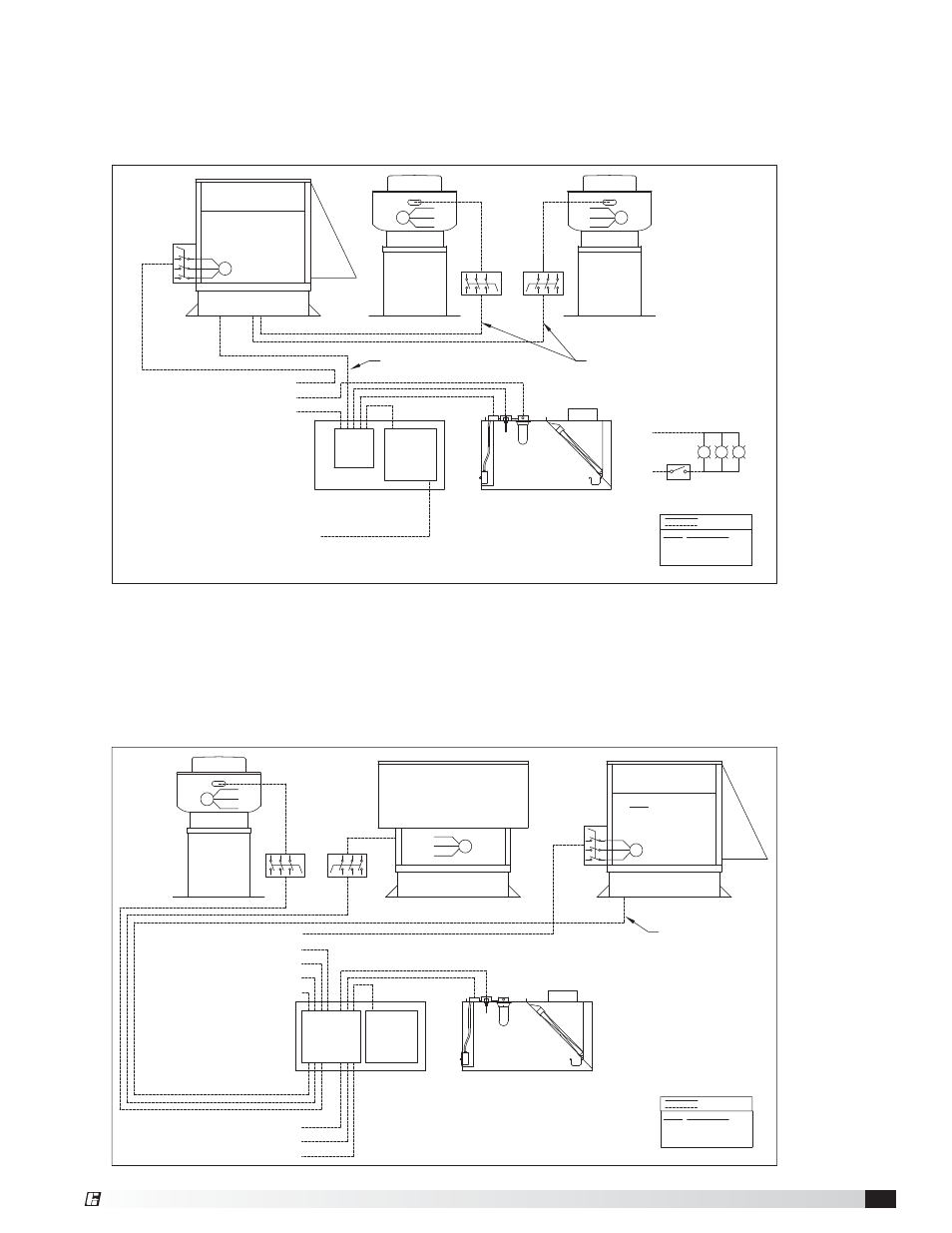
Overall Wiring Plan View for Kitchen Systems with Make-Up Air Control Centers
In this arrangement, single-point power to the make-up air (MUA) unit is fed to each individual exhaust fan
disconnect from exhaust fan starters within the MUA control center. This arrangement can be used for constant
volume systems only. The diagram below is generic. To see your job specific wiring requirements, refer to the wiring
diagrams provided with the package.
Overall Wiring Plan View for Kitchen Systems with Kitchen Fan Control Centers
This arrangement requires individual power connections for each supply and exhaust fan from remote circuit
breakers through the fan starters in the Kitchen Fan Control Center (KFCC) or variable frequency drives in the
Variable Volume Control Package. This arrangement can be used for either constant volume or variable volume
systems. The diagram below is generic. To see your job specific wiring requirements, refer to the wiring diagrams
provided with the package.