Ansul wiring plan view, Kitchen hoods • type i and type ii 26 – Greenheck Canopy Hoods (452413 IOM) User Manual
Page 26
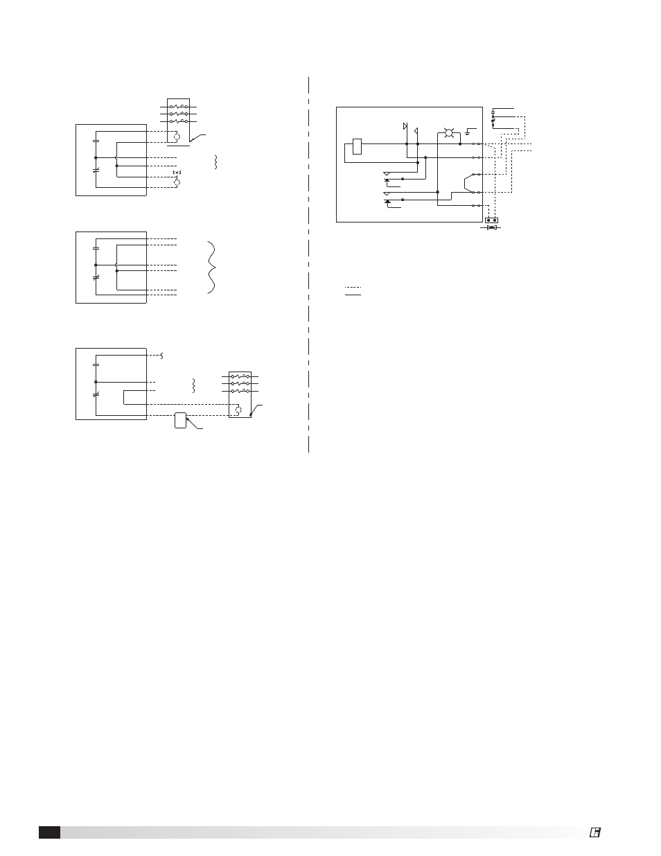
Kitchen Hoods • Type I and Type II
26
®
Manual Reset Relay
Part No. 426151
Ansul Snap-Action Switch
Part No. 423878
Switch contacts shown with Ansul
Automan in the cocked position
Black
Red
Brown
L2 Neutral
L1 Hot
110 VAC/60Hz
5
4
3
2
1
GND
Screw
Power
Indicator
Reset
A
B
Relay Coil
Electrical Rating
1/3 HP, 10 AMP, 120 VAC
1/2 HP, 10 AMP, 240 VAC
13 AMP, 28 VDC
Gas Valve
See Note 3
6
9
3
4
7
1
Snap-Action Switches may be wired as shown.
Typical examples shown.
Power to cooking
equipment
Shunt Trip Breaker
120 VAC
N
Input
NO
NC
Electric gas valve - If reset relay is
used, see option A or B at right.
Mechanical gas shut off valve does not
require electrical connection.
NO
NC
NO
Input
NC
Voltage Free
Contacts for
Building Alarm(s)
NO
NC
120 VAC
N
Input
Power to
fan(s)
Fan Starter
Manual Switch
If prohibited by local codes, do not shut down
exhaust fans with this method of wiring.
Note:
1.
Denotes field installation.
2.
Denotes factory installation.
3. Gas Valves: “UL Listed electrically-operated safety valve for natural or LP gas
as needed, of appropriate pressure and temperature rating, 110V/60Hz”
or Ansul gas valves.
4. Do not use black wire on snap-action switch in normal installation. Black
wire may only be used for extraneous alarm, light circuits, etc.
Equipment
Alarms
Fans
Ansul Wiring Plan View