Greenheck Canopy Hoods (452413 IOM) User Manual
Page 21
Kitchen Hoods • Type I and Type II
21
®
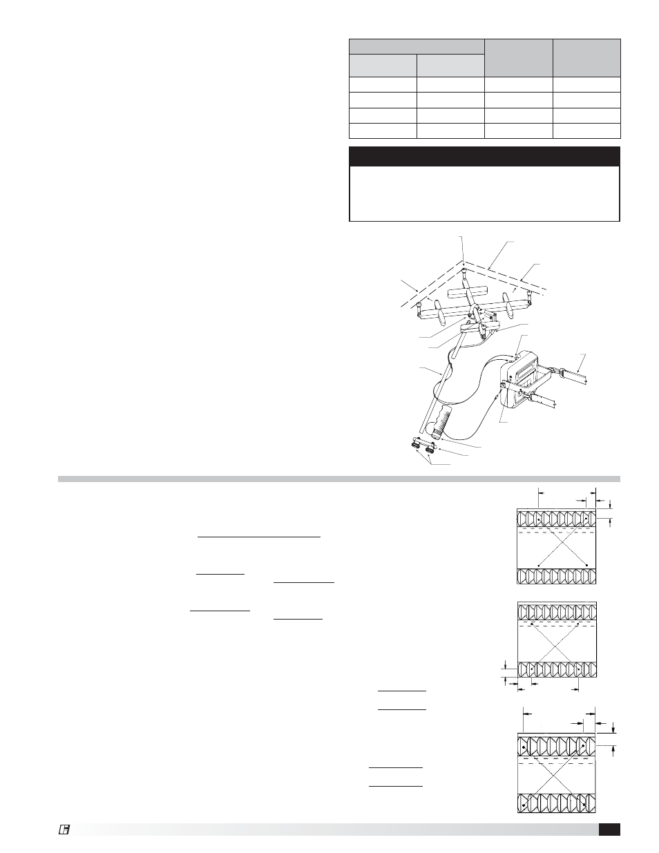
14.25 in.
(361.95 mm)
14.25 in.
(361.95 mm)
2.75 in.
(69.85 mm)
2.75 in.
(69.85 mm)
2.75 in.
(69.85 mm)
2.75 in.
(69.85 mm)
Fig. 16
14.25 in.
(361.95 mm)
14.25 in.
(361.95 mm)
2.75 in.
(69.85 mm)
2.75 in.
(69.85 mm)
2.75 in.
(69.85 mm)
2.75 in.
(69.85 mm)
Fig. 18
14.75 in.
(374.65 mm)
14.75 in.
(374.65 mm)
3.25 in.
(82.55 mm)
3.25 in.
(82.55 mm)
2.5 in.
(63.5 mm)
2.5 in.
(63.5 mm)
Fig. 17
Nominal Filter Size (H x L)
Imperial
Conversion
Factor
Metric
Conversion
Factor
Inches
Millimeters
16 x 16
400 x 400
1.53
ft
2
.142
m
2
16 x 20
400 x 500
2.00
ft
2
.185
m
2
20 x 16
500 x 400
2.25
ft
2
.209
m
2
20 x 20
500 x 500
3.00
ft
2
.279
m
2
NOTE
For best accuracy multiply the velocity of each filter
by its conversion factor and sum the flow rates.
Averaging the velocity measured for all filters may
cause error.
Grease-X-Tractor™ High Efficiency Filters
or Grease Grabber™ Multi-Filtration System
Shortridge Method
With all the filters in place, determine the total hood
exhaust volume with a Shortridge meter as follows:
1. All cooking equipment should be on. If the hood has
internal short circuit make-up air, it should be turned off.
2. Measure velocities
•
Set up the Shortridge meter. Leave all holes of
VelGrid open. Do NOT tape over holes that are not
over openings. The conversion factor takes this
into account.
•
For 20 in. (500 mm) high filters, position the grid
as shown in Fig. 16 and 17. Average the two
measurements.
•
For 16 in. (400 mm) high filters position the grid as
shown in Fig. 18.
•
For 20 in. (500 mm) wide filters, position the grid
over the left and right side of the filter. Average the
two measurements.
• Take velocity readings for each filter.
3. Calculate each filter’s volumetric flow rate as follows:
Calculate each filter’s average velocity by summing
the velocity readings and dividing by the number of
readings for each filter.
Multiply the average velocity by the conversion factor
to obtain the volumetric flow rate for each filter.
4. Calculate the hood’s total volumetric flow rate by
summing the volumetric flow rate of each individual
filter in the hood as calculated in Step 3.
Average Slot Velocity =
Sum of Velocity Readings
Number of Readings
(Imperial)
=
198 + 205
2
= 201.5 ft/min.
(Metric)
=
3021 + 3749
2
= 3385 m/hr
Total hood flow rate
= (Filter 1 Flow Rate) +
…
+ (Filter x Flow Rate)
(Imperial)
= 604.5 + 600.3 + 592.4 + 613.3 =
2410.5 cfm
(Metric)
= 944 + 1020 + 1006 + 1042
=
4012 m
3
/hr
Flow rate for one filter =
Conversion
Factor
x
Average
Velocity
(Imperial)
=
3.0
x
201.5 ft/min.
=
604.5 cfm
(Metric)
=
.279
x
3385 m/hr
=
944 m
3
/hr
Edge of outlet/inlet
active face area
Maintain 1½ inch
(38.1 mm) margin
Maintain 1½ inch
(38.1 mm) margin
Place standoff spacers against
face of outlet or inlet grill,
filter, coil, etc.
Tubing harness
Neckstrap
External read jack
Extension rods
Swivel bracket
Tubing connectors
Pushbutton handle and plug
Handle bracket
Captive knob screws
Pressure input ports
Example: Measured velocities for 20 x 20 in. (500 x 500 mm) filter.