GAI-Tronics 12514-004, 12514-005, 12514-006 Thermoplastic Elastomer Cord Kits User Manual
Page 3
Pub. 42003-026C
T
HERMOPLASTIC
E
LASTOMER
C
ORD
R
EPLACEMENT
K
IT
Page:
3 of 11
\\s_eng\gtcproddocs\standard ioms - current release\42003 kit manuals\42003-026c.doc
7/00
Installation of New Cord
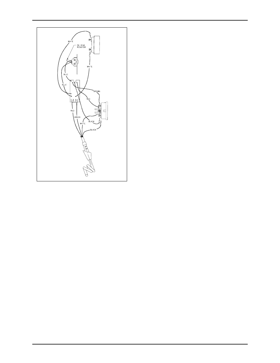
9. Snip off the cord’s blue and yellow wires as close to
their origin as possible. Insert the wire harness from
the new cord into the handset. Refer to Figure 2.
10. Connect the red and green cord wires to the Receiver
Amplifier PCBA. Replace the receiver and the
receiver cap.
11. Connect the black and white cord wires to the
transmitter cup. Re-connect the black, brown, and
red wires of the Receiver Amplifier PCBA to the
transmitter cup. Replace the transmitter cup,
transmitter, and cap. Note the notch on the
transmitter cup. When placing the transmitter cup in
the handset, align the notch to catch the bushing on
the coil cord to secure the cord firmly in the handset.
12. Insert the end of the new cord through the front panel
until the bushing is flush against the panel.
13. Press the bushing tight against the front panel, and
insert the handset cord fastener clip onto the rear of
the bushing, against the back side of the front panel.
14. Reconnect the 4 telephone wires to the PCBA as
follows:
Red to E1
Green to E2
White to E3
Black to E4
15. Reconnect the modular telephone wire to the RJ11
jack on the PCBA, and fasten the front panel to the
rear enclosure.
Models 9001, 9005, 9081, and 9085
Removal of Old Cord
1. Unscrew the 4 front panel captive screws and open the front panel. Unsnap the blue ribbon cable from
the back panel of the station. Loosen the interior hinges and remove the front panel.
2. Remove the 5 screws securing the back box to the printed circuit board assembly (PCBA). Remove
the back box.
3. Identify if your station is an older or a newer model. The older models have an unsecured terminal that
is not anchored to the printed circuit board.
For older models: Disconnect the wires from the PCBA.
Red from E1
White from E2
Black from E3
Yellow from E4
Blue from E5
Green from the unsecured terminal.
For newer models: Disconnect the wires from the PCBA.
Red from E1
Green from E2
Black from E3
Yellow from E4
Blue from E5
White from E7
4. When replacing a PVC cord, use a Heyco
®
bushing tool or a needle nose pliers to squeeze the notch on
the front panel side of the strain relief bushing and pull out the bushing.
5. Feed the bushing and the wires through the front panel to free the cord from the panel.
Figure 2. Handset Wiring Diagram