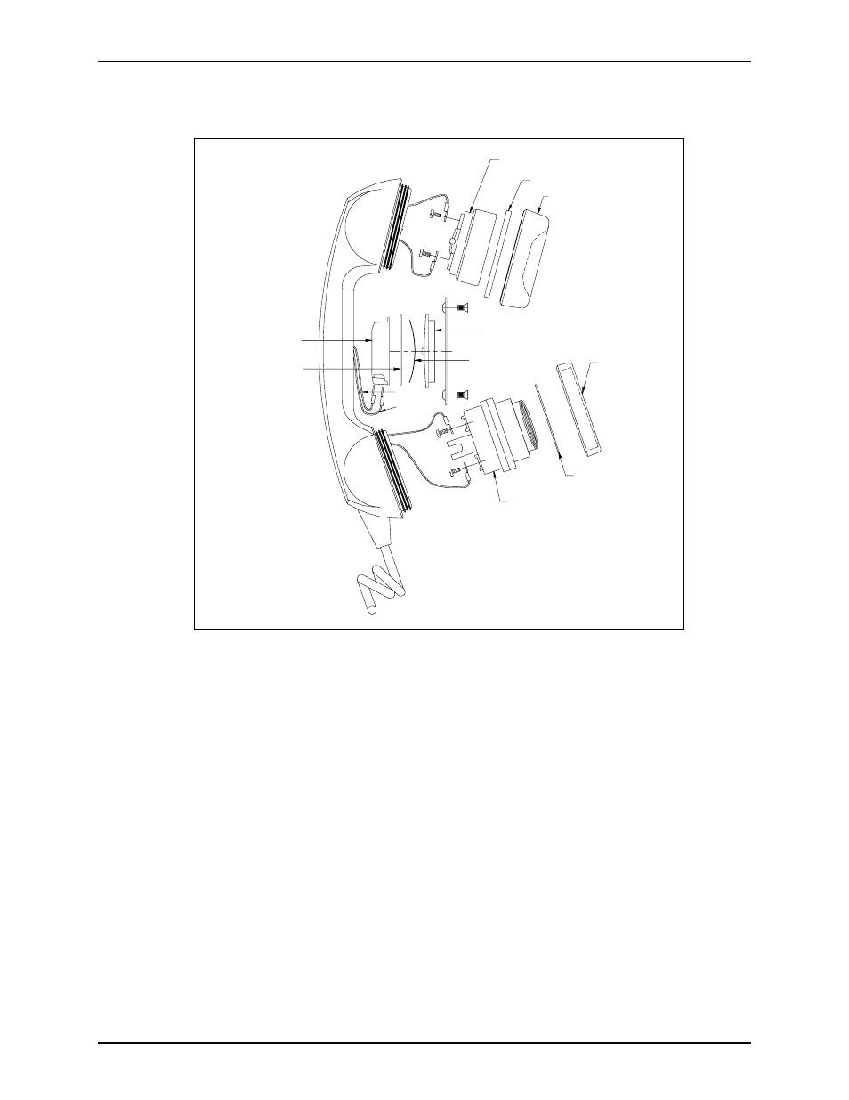
2 of 11, When replacing an existing pvc cord, use a heyco, Figure 1. handset outline diagram – GAI-Tronics 12514-004, 12514-005, 12514-006 Thermoplastic Elastomer Cord Kits User Manual
Page 2
Pub. 42003-026C
T
HERMOPLASTIC
E
LASTOMER
C
ORD
R
EPLACEMENT
K
IT
Page:
2 of 11
\\s_eng\gtcproddocs\standard ioms - current release\42003 kit manuals\42003-026c.doc
7/00
3. When replacing an existing PVC cord, use a Heyco
®
bushing tool or a needle nose pliers to squeeze the
notch on the front panel side of the strain relief bushing and pull out the bushing.
4. When replacing a thermoplastic elastomer cord, remove the handset cord fastener clip located on the
back side of the front panel. The fastener clip secures the bushing and the cord to the front panel.
5. Pull the old cord through the front panel and set aside.
6. Remove the lower cap from the handset. Lift out the transmitter and the transmitter cup. Disconnect
both wires.
7. Remove the receiver cap, lift out the receiver and disconnect both wires.
8. Pull the wire harness out of the handset.
YELLOW
BLUE
BLACK
WHITE
GREEN
RED
TRANSMITTER
CAP
WASHER
TRANSMITTER
RECEIVER
CAP
GASKET
RECEIVER
PLASTIC CUP
PRESSBAR
COPPER SPRING
COPPER PLUNGER
Figure 1. Handset Outline Diagram
- 370-201, 372A Interface Amplifier Assembly (10 pages)
- 13314-001 and 13314-002 Div. 2 Hazardous Area Speaker Assembly using 13314 Driver (3 pages)
- 230-001 Pole-Mounting Kit (3 pages)
- Electro Sound Electro-Sound Communication System (9 pages)
- 13314-004 Div. 2 Hazardous Area 100-Volt Horn Driver (5 pages)
- XGM003A Gooseneck Microphone Kit (5 pages)
- XGM003A Gooseneck Microphone Kit (2 pages)
- XGM003A Gooseneck Microphone Kit (26 pages)
- 9974 Junction Box (5 pages)
- 232-001 Pole Mounting Kit (3 pages)
- 13411-001 and 13411-002 Replacement Voice Coil / Diaphragm Assemblies (5 pages)
- 726-101 Single Party Desktop Subset (5 pages)
- 726-101 Single Party Desktop Subset (4 pages)
- 478-002 Centra-Page Desktop Subset (6 pages)
- 210-001 Corridor Telephone (10 pages)
- 239WM-002 Slim Wall-Mount Stanchions (10 pages)
- 239WM-002 Slim Wall-Mount Stanchions (5 pages)
- 239WM-002 Slim Wall-Mount Stanchions (6 pages)
- 239WM-002 Slim Wall-Mount Stanchions (4 pages)
- 239WM-002 Slim Wall-Mount Stanchions (4 pages)
- Speaker / Horn Installation for GAI-Tronics Communication System (8 pages)
- 700 Series 120 V AC Page/Party Systems (10 pages)
- 700 Series 24 V DC Page/Party Systems (14 pages)
- 703-002 Multi-Party 24 V DC Amplifier Enclosures (13 pages)
- 703A Indoor Multi-Party 115 V AC Amplifier Enclosure (3 pages)
- 703A Indoor Multi-Party 115 V AC Amplifier Enclosure (8 pages)
- 723-001 Remote Handset / Speaker Amplifier (3 pages)
- 723-003 24 V DC Remote Handset/Speaker Amplifier (7 pages)
- 237-001 Plug-in Power Supply for Telephones (3 pages)
- 733-002 Single Party 24 V DC Amplifier Enclosure (13 pages)
- 7855-001 Explosion-proof Handset Stations (13 pages)
- 7855-002 24 V DC Explosion-proof Page/Party Handset Stations (14 pages)
- 670-001 Explosion-proof Page/Party Speaker Station (9 pages)
- 670-002 24 V DC Explosion-proof Page/Party Speaker Station (10 pages)
- 13351 Integral Loudspeakers (5 pages)
- 305-001 Line Balance Assembly (3 pages)
- 272-001 Intrinsically-Safe Telephones (13 pages)
- 713-102 24 V DC Page/Party Remote Speaker Amplifier (5 pages)
- 263-000 Isolation Barrier Unit (I.S. Phone) (14 pages)
- 774-001 Portable Station Enclosure (Page/Party) (5 pages)
- 234SBA 234SBA Stanchion Broadcast Assembly (12 pages)
- 491-204 Mine Dial / Page Phone (10 pages)
- 773-001 Outdoor Jack Station (Page/Party) (3 pages)
- 491 Series Mine Dial / Page Phone Interface Cabinet (23 pages)
- 268-001 Intrinsically-Safe Telephone Rack-Mount System (14 pages)