GAI-Tronics SSM110 Card Rack Assembly User Manual
Page 7
Pub. 42004-669L2E
SSM110 Card Rack Assembly Installation, Operation, Maintenance Manual
Page: 5 of 26
\\s_eng\gtcproddocs\standard ioms - current release\42004 instr. manuals\42004-669l2e.doc
07/07
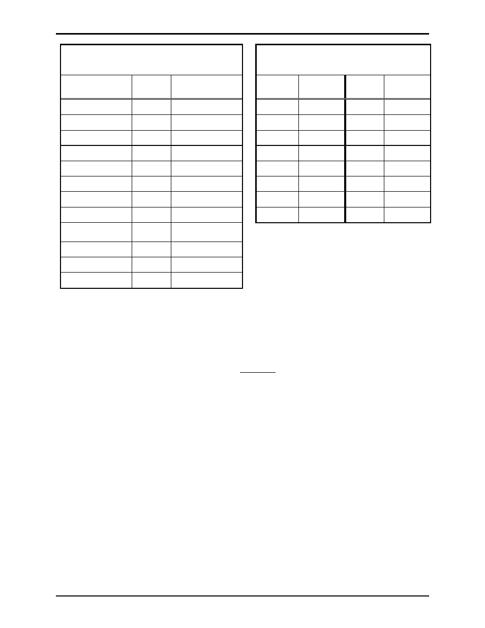
Table 1. Connections Wiring
Page/Party
®
System Cable
Table 2. Wiring
Access Panel Connections
Audio Line
Terminal
System Cable
Color Code
Access
Panel
Terminal
Access
Panel
Terminal
Page Line (L1)
1
Red/blue
#1 (+)
1
#5 (+)
9
Page Line (L2)
2
Blue/red
#1 (-)
2
#5 (-)
10
Party Line 1 (L1)
3
Red
#2 (+)
3
#6 (+)
11
Party Line 1 (L2)
4
Tan/red
#2 (-)
4
#6 (-)
12
Party Line 2 (L1)
5
Violet
#3 (+)
5
#7 (+)
13
Party Line 2 (L2)
6
Tan/violet
#3 (-)
6
#7 (-)
14
Party Line 3 (L1)
11
Blue
#4 (+)
7
#8 (+)
15
Party Line 3 (L2)
12
Tan/blue
#4 (-)
8
#8 (-)
16
Party Line 4 (L1)
13
Brown
One No. 18 AWG twisted pair cable is required for
each access panel.
Party Line 4 (L2)
14
Tan/brown
Party Line 5 (L1)
15
Yellow
Party Line 5 (L2)
16
Tan/yellow
GAI-Tronics 8- or 16-conductor cable is
required.
To attach the wires to the plug:
1. Turn the plug screws counterclockwise several times to open the terminal.
2. For optimum wire connection, crimp a ferrule on the end of each wire, then insert the ferrule into the
plug. If not using a ferrule, verify that there are no strands of wire extruding from the plug after the
wire is inserted.
3. Secure the wire by turning the screw clockwise.
4. Gently pull on the wire to verify that the wire is secured tightly in the plug.
5. After all wires are terminated, insert the plug into the receptacle and then tighten the screws on either
end of the plug.