Central amplifier failure inputs, Speaker loop interfaces – GAI-Tronics 12580-001 Audio Distribution Module User Manual
Page 8
Pub. 42004-600L2C
Model 12580-001 Amplifier Distribution/Monitor Module
Page: 8 of 17
f:\standard ioms - current release\42004 instr. manuals\42004-600l2c.doc
10/11
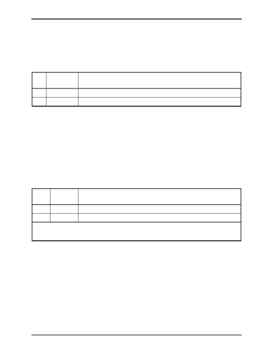
Central Amplifier Failure Inputs
The ADM contains six 2-position terminal blocks (TB1, TB4, TB7, TB10, TB13, and TB16) to receive
central amplifier failure contacts. A normally open or normally closed dry contact closure input is
provided for each amplifier. The pinout for the central amplifier failure inputs is shown in Table 6.
Table 6. Central Amplifier Failure Inputs - TB1, TB4, TB7, TB10, TB13, and TB16 Pinouts
Pin
No.
Function
Description
1
CCIN
+
Connects to one leg of a central amplifier’s contact closure (input)
2
CCIN
−
Connects to the other leg of a central amplifier’s contact closure (input)
Speaker Loop Interfaces
The ADM contains six 2-position terminal blocks (TB3, TB6, TB9, TB12, TB15, and TB18) to enable
termination of the six central amplifier speaker loops. The ADM monitors the speaker loops for ground
faults, cable breaks*, wire-to-wire shorts*, and amplifier failures. The pinout for TB3, TB6, TB9, TB12,
TB15, and TB18
is shown in Table 7.
N
OTES
:
• (*) indicates that fault detection occurs only while the associated amplifier is not in use.
• Only one voltage type (25 V, 70 V, etc.) may be supervised at a time.
Table 7. Speaker Loop Interfaces TB3, TB6, TB9, TB12, TB15, and TB18 Pinouts
Pin
No.
Function
Description
1
SPKR
Connects to one leg of a central amplifier’s speaker loop (input)
2
SPKR
Connects to the other leg of a central amplifier’s speaker loop (input)
N
OTE
: The conductors terminated on these terminal blocks should be twisted pairs. These connections
are not polarity-sensitive.