Acc2500 audio control center desk set connections, Telephone line connections – GAI-Tronics 10959-908 Rack-Mount Audio Messenger Interfaces User Manual
Page 12
Pub. 42004-487A
M
ODEL
10959-906
&
10959-908
R
ACK
-M
OUNT
A
UDIO
M
ESSENGER
I
NTERFACES
P
AGE
10 of 18
f:\standard ioms - current release\42004 instr. manuals\42004-487a.doc
01/14
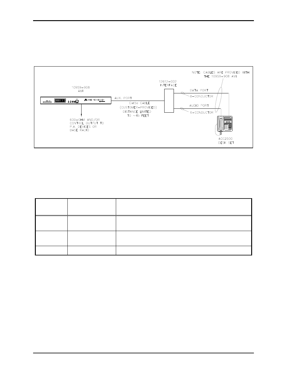
ACC2500 Audio Control Center Desk Set Connections
Connecting the AMI to the ACC2500 Desk Set requires a Model 12612-002 Interface and two modular
cables. All three items are provided with the AMI. A customer provided, 8-conductor, Cat5 Ethernet
cable of up to 45 feet in length must be connected from the 12612-002 Interface to Ethernet connector J1
(on the termination PCBA) in the AMI. Refer to Figure 4 for interconnection details.
Figure 4. Typical ACC2500 Connection Diagram
Power Connection
The terminal block TB6, labeled
CLASS
2
12–24
VDC
, is located on the Termination PCBA. It provides
power connection for the AMI.
Table 3. Power Assignment
Metalwork
Label
Internal
Terminal Pin-Out
Function or ACT Description
+
TB6-1
Positive terminal of external power supply (Black wire with
white stripe from power supply)
−
TB6-2
Negative terminal of external power supply (Solid black wire
from power supply)
GND TB6-3
Frame
ground
Telephone Line Connections
The Model 10959-906 and 10959-908 Audio Messenger Interfaces are each equipped with a Telephone
Interface PCBA. Connections are made from the AMI to a standard PBX analog station port or directly
to a Central Office (C.O.) telephone line. The incoming telephone line must be connected to the tip (E1)
and ring (E2) of the Telephone Interface PCBA. The AMI includes a telephone line cord with modular
RJ-11 plug.
N
OTE
: Telephone interface operation requires a minimum loop current of 25 mA.