Control output connections – GAI-Tronics 10959-908 Rack-Mount Audio Messenger Interfaces User Manual
Page 11
Pub. 42004-487A
M
ODEL
10959-906
&
10959-908
R
ACK
-M
OUNT
A
UDIO
M
ESSENGER
I
NTERFACES
P
AGE
9 of 18
f:\standard ioms - current release\42004 instr. manuals\42004-487a.doc
01/14
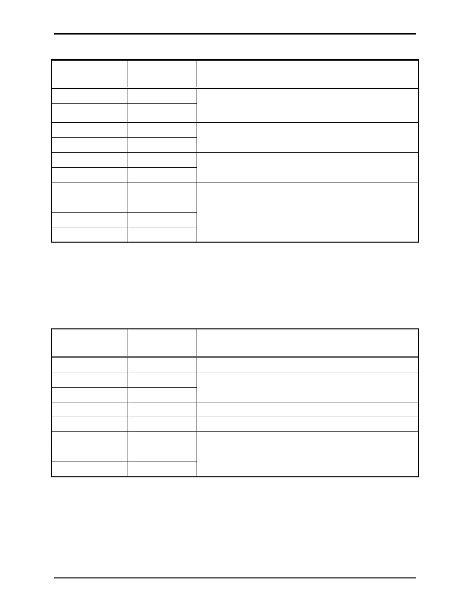
Table 1. Audio Assignment
Termination PCBA
Label
Internal Terminal
Pin-Out
Function or ACT Description
600-ohm L1
TB3-1
600-ohm audio pair to distribution amplifier cabinet,
Stanchion Broadcast electronics module, Addressable
Amplified Speaker, or other 600-ohm compatible devices.
600-ohm L2
TB3-2
AUDBUS2 L1
TB3-3
No connection
AUDBUS2 L2
TB3-4
AUDBUS1 L1
TB3-5
No connection
AUDBUS1 L2
TB3-6
PGND TB3-7
No
connection
RS485 INT GND
TB3-8
No connection
RS485 INT− TB3-9
RS485 INT+
TB3-10
Control Output Connections
Terminal block TB4, labeled
SYSTEM
, is located on the Termination PCBA. It provides connection for a
contact closure output to activate the public address system (central amplifier input, Amplified
Addressable Speaker input, etc.).
Table 2. System Assignment
Termination PCBA
Label
Internal Terminal
Pin-Out
Function or ACT Description
EXT DATA GND
TB4-1
No connection
EXT DATA − TB4-2
No connection
EXT DATA +
TB4-3
FLT TB4-4
No
connection
REBOOT TB4-5 No
connection
GND TB4-6
No
connection
AUD ACT 1
TB4-7
Isolated solid state relay, closed during AMI broadcast
On resistance = 30 ohms
AUD ACT 2
TB4-8
The following connections are not used by the Model 10959-906 and 10959-908 Audio Messenger
Interfaces:
•
Digital outputs (TB1)
•
Digital inputs (TB2)
•
Auxiliary Audio (TB5)